
Description
-
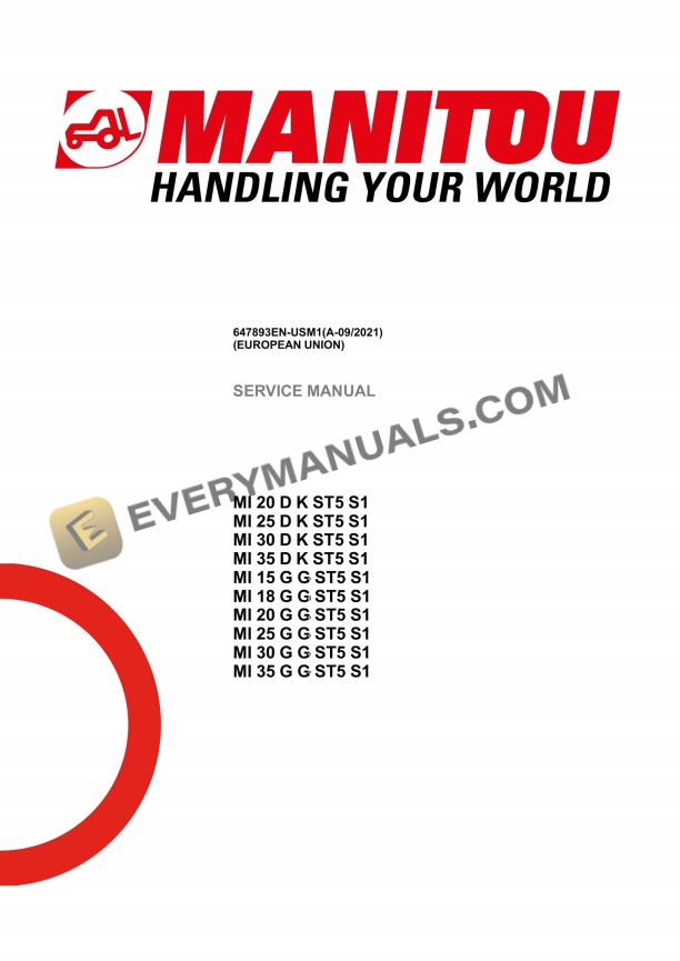
Model List:
- MI 20 D K ST5 S1
- MI 25 D K ST5 S1
- MI 30 D K ST5 S1
- MI 35 D K ST5 S1
- MI 15 G G ST5 S1
- MI 18 G G ST5 S1
- MI 20 G G ST5 S1
- MI 25 G G ST5 S1
- MI 30 G G ST5 S1
- MI 35 G G ST5 S1
- 1. Legal disclaimer
- 2. Foreword
- 3. Intervention during the warranty period
- 4. Supplier Documentation List
- 5. Safety
- 5.1. Servicing position
- 5.2. Servicing Rules
- 6. Reference Information
- 6.1. Explanation of symbols
- 6.2. Metric imperial unit conversion
- 6.3. List of Abbreviations
- 6.4. Standard tightening torques
- 7. Characteristics and Specifications
- 7.1. Technical Datasheet MI 20 D K ST5 S1
- 7.2. Technical Datasheet MI 25 D K ST5 S1
- 7.3. Technical Datasheet MI 30 D K ST5 S1
- 7.4. Technical Datasheet MI 35 D K ST5 S1
- 7.5. Technical Datasheet MI 15 G G ST5 S1
- 7.6. Technical Datasheet MI 18 G G ST5 S1
- 7.7. Technical Datasheet MI 20 G G ST5 S1
- 7.8. Technical Datasheet MI 25 G G ST5 S1
- 7.9. Technical Datasheet MI 30 G G ST5 S1
- 7.10. Technical Datasheet MI 35 G G ST5 S1
- 8. Supplier Documentation
- 9. Characteristics and Specifications
- 9.1. Power system
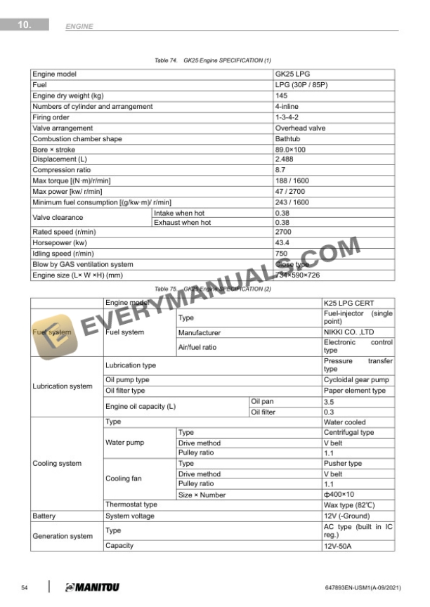
- 9.2. Petrol engine GK21 and GK25 LPG operation
- 9.3. Engine Characteristics And Specifications
- 9.4. GCT (NISSAN) GK21/GK25 Gasoline
- 9.5. GK21/GK25 Maintenance
- 9.6. V2607CrE5b Specifications
- 9.7. Air Inlet System
- 9.8. Exhaust system MI G
- 9.9. Exhaust system MI D
- 9.10. Cooling system
- 10. Location
- 10.1. Engine mount
- 10.2. Engine Components MI G
- 10.3. Engine Components MI D
- 11. Removal
- 11.1. Removal Of The DPF
- 11.2. Removal Of The Exhaust Line
- 11.3. Removal Of The Coolant Expansion Tank
- 11.4. Removal Of The Air Filter Box
- 11.5. Removal Of The Alternator
- 11.6. Removal Of The Starter
- 11.7. Removal Of The Radiator
- 11.8. Removal Of The Engine
- 11.9. Removal Of The Fan Belt
- 12. Troubleshooting
- 12.1. Gas Engine GK21 GK25
- 12.2. Engine Diagnostic Codes (Refer to Section 120)
- 13. Specific Tools
- 13.1. Electronic belt tensiometer
- 13.2. Elastic belt specific tools
- 14. Supplier Documentation
- 15. Characteristics and Specifications
- 15.1. Overview/Summary
- 15.2. GearBox Hoisting Diagram
- 15.3. Working Principle
- 15.4. Hydraulic Transmission Box Structure
- 16. Removal
- 16.1. General Information
- 16.2. Preparation And Safety Instructions
- 16.3. Disassembly Procedures
- 16.4. Assembling Procedures
- 16.5. Gearbox Removal
- 17. Troubleshooting
- 17.1. Troubleshoot
- 18. Driving axle
- 18.1. Data
- 18.2. Trouble Diagnoses And Corrections
- 18.3. Driving Axle Assemble Removal And Installation
- 18.4. Axle Shaft And Wheel Hub
- 18.5. Removal
- 18.6. Inspection
- 18.7. Installation
- 18.8. Bearing Adjustment
- 19. Steering Axle
- 19.1. Trouble Diagnoses Corrections
- 19.2. Structure, Disassembly And Installation
- 19.3. Steering Axle
- 19.4. Kingpin And Steering Spindle
- 19.5. Inspection
- 19.6. Installation
- 19.7. Wheel Bearing Adjustment
- 19.8. Steering Cylinder
- 19.9. Disassemble
- 19.10. Installation
- 20. Steering system
- 20.1. Summarize
- 20.2. Data
- 20.3. Full Hydrostatic Power Steering Gear Assemble
- 20.4. Full Hydrostatic Power Steering Gear
- 20.5. Steering Cylinder
- 20.6. Steering System Installation
- 20.7. Trouble Diagnoses
- 21. Characteristics and Specifications
- 21.1. Summary
- 21.2. Master Cylinder
- 21.3. Brake
- 22. Control and Adjustment
- 22.1. Adjusting The Inching and Brake Pedal
- 22.2. Hand Brake Device
- 22.3. Replace Brake Shoe
- 23. Removal
- 23.1. Dissasembling The Front Wheel Brake
- 24. Refit
- 24.1. Refitting the front wheel brake
- 25. Troubleshooting
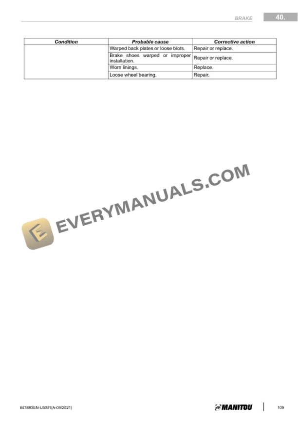
- 25.1. Trouble Diagnoses And Corrections
- 26. Characteristics and Specifications
- 26.1. Assemble Debugging Data
- 26.2. Trouble Diagnoses And Corrections
- 26.3. Summary
- 26.4. Double High Visibility Mast
- 26.5. Double Full Free Lift Mast (Including Container Mast)
- 26.6. Triple Full Free Lift Mast
- 27. Control and Adjustment
- 27.1. Removal And Adjustment
- 27.2. Removal Of Forks And Mast Assembly
- 27.3. Disassembly
- 27.4. Removal Of The Lifting Jack
- 27.5. Removal Of The Inner Mast
- 27.6. Inspection
- 27.7. Assembly And Adjustment
- 27.8. Lift Roller
- 27.9. Left And Right Cylinder Height Initial Adjustment
- 27.10. Lifting Chain Adjustment
- 27.11. Clearance of fork arm CARA
- 27.12. Removal Of The Roller
- 28. Removal
- 28.1. Disassembly and installation of lifting jack
- 28.2. Disassembly and installation of tilting cylinder
- 28.3. Noticing Proceeding Of Debugging
- 29. Characteristics and Specifications
- 29.1. Main pump
- 29.2. Multiway valve
- 30. Schematics
- 30.1. Hydraulic Piping or Schematics
- 31. Removal
- 31.1. Removal Of The Hydraulic Pump
- 31.2. Removal Of The Hydraulic Dispenser
- 31.3. Removal Of The Tilt Cylinders
- 32. Troubleshooting
- 32.1. Trouble Diagnoses And Corrections
- 33. Specific Tools
- 33.1. Digital manometer kit
- 33.2. Basic manometer kit
- 34. Characteristics and Specifications
- 34.1. Fuse Location
- 34.2. Electronic Control Unit
- 34.3. Lighting System
- 34.4. Key (start) switch
- 34.5. Reverse Buzzer
- 34.6. Brake Lamps Switch
- 34.7. PreHeat And Start Switch
- 34.8. Combination Switch Assembly
- 34.9. Water Temperature Sensor
- 34.10. Fuel Gauge Sensor
- 34.11. Fuel Pressure Warner
- 34.12. Backup Buzzer/Reverse Warner
- 34.13. HandBrake Switch Assembly
- 34.14. Reversing Solenoid Valve
- 35. Schematics
- 35.1. Position per diagram MI 1535 G ST5
- 35.2. MI 1535 G ST5 Electrical Schematic
- 35.3. Position per diagram MI 2035 D ST5
- 35.4. MI 2035 D ST5 Electrical Schematic
- 36. Location
- 36.1. Location of electrical system components
- 37. Removal
- 37.1. Removal Of The Battery
- 37.2. Removal of the Engine Calculator
- 37.3. Removal of the Hydraulic Distributor Computer
- 38. Specific Tools
- 38.1. Breakout boxes
- 39. Interactive Instrument
- 39.1. Interactive Instrument
- 39.2. Engine fault information display page
- 39.3. Forklift operation parameters
- 39.4. Settings Page
- 39.5. Disassembly and installation
- 40. Removal
- 40.1. Cabin Components
- 40.2. Removal Of Lpg Cylinder
- 40.3. Removal Of Cabin
- 40.4. Disassembly Procedure
- 40.5. Removal Of The Drivers Seat Cover
- 40.6. Drop The Floor Of The Workstation
- 40.7. Open The Drivers Seat Hood
- 41. Removal
- 41.1. Counter Weight Removal
- 41.2. Removal Of The Counterweight
- 42. Optional mini levers
- 42.1. Characteristics and Specifications
- 42.2. Hydraulics
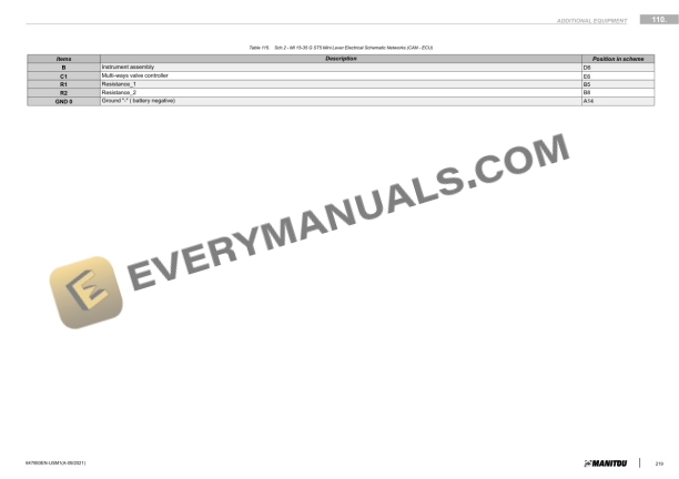
- 42.3. Electrical Diagram
- 42.4. Location
- 42.5. Control and Adjustments
- 42.6. Troubleshooting
- 43. Engine diagnostics
- 44. DTC engine ECU diagnosis (V2607 ST5)
- 45. DTC engine ECU diagnosis (GK21/25)
- 46. Diagnostics tools Kubota DIAGMASTER (DSTi)
- 46.1. KUBOTA engine diagnostics tool Diagmaster