
Description
-
Model List:
- MLT 740 H LSU Turbo Serie 1
- MT 1033 HL Turbo Serie 1
- 1. GROUP_0_547842EN
- 1.1. GROUP 0
- 1.1.1. LIFT TRUCK CHARACTERISTICS
- 2. GROUP_10_547842EN
- 2.1. GROUP 10
- 2.1.1. DISASSEMBLY OF THE I.C. ENGINE
- 2.1.1.1. Contents
- 2.1.1.2. Chapter 10 General information
- 2.1.1.2.1. Introduction
- 2.1.1.2.2. Engine identification
- 2.1.1.2.3. General safety precautions
- 2.1.1.2.4. Engine lift equipment
- 2.1.1.2.5. Viton seals
- 2.1.1.2.6. POWERPART recommended consumable products
- 2.1.1.3. Chapter 11 Specifications
- 2.1.1.3.1. Basic engine data
- 2.1.1.3.2. Thread sealant
- 2.1.1.3.3. Standard torque tensions
- 2.1.1.3.4. Specific torque tensions
- 2.1.1.3.5. Compression test data
- 2.1.1.4. Chapter 12 Cylinder head assembly
- 2.1.1.4.1. General description
- 2.1.1.4.2. Rocker cover
- 2.1.1.4.3. Rocker assembly
- 2.1.1.4.4. Valve tip clearances
- 2.1.1.4.5. Valve springs
- 2.1.1.4.6. Cylinder head assembly
- 2.1.1.4.7. Valves and valve springs
- 2.1.1.4.8. Valve guides
- 2.1.1.4.9. Cylinder head
- 2.1.1.4.10. Data and dimensions
- 2.1.1.5. Chapter 13 Piston and connecting rod assemblies
- 2.1.1.5.1. General description
- 2.1.1.5.2. Big end bearing
- 2.1.1.5.3. Piston and connecting rod
- 2.1.1.5.4. Piston rings
- 2.1.1.5.5. Piston and connecting rod assembly
- 2.1.1.5.6. Piston and piston rings
- 2.1.1.5.7. Connecting rod
- 2.1.1.5.8. Partially finished small end bush
- 2.1.1.5.9. Piston cooling jets
- 2.1.1.5.10. Data and dimensions
- 2.1.1.6. Chapter 14 Crankshaft assembly
- 2.1.1.6.1. General description
- 2.1.1.6.2. Crankshaft pulley
- 2.1.1.6.3. Crankshaft pulley and damper
- 2.1.1.6.4. Rear oil seal assembly
- 2.1.1.6.5. Thrust washers
- 2.1.1.6.6. Main bearings
- 2.1.1.6.7. Crankshaft
- 2.1.1.6.8. Balancer unit
- 2.1.1.6.9. Data and dimensions
- 2.1.1.7. Chapter 15 Timing case and drive assembly
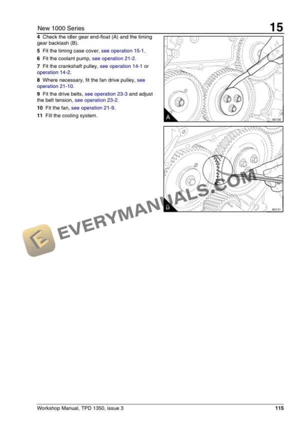
- 2.1.1.7.1. General description
- 2.1.1.7.2. Timing case cover
- 2.1.1.7.3. Front oil seal
- 2.1.1.7.4. Idler gear and hub
- 2.1.1.7.5. Idler gear and hub for the Bendix compressor
- 2.1.1.7.6. Fuel pump gear
- 2.1.1.7.7. Camshaft gear
- 2.1.1.7.8. Crankshaft gear
- 2.1.1.7.9. Timing case
- 2.1.1.7.10. Camshaft and tappets
- 2.1.1.7.11. Data and dimensions
- 2.1.1.8. Chapter 16 Cylinder block assembly
- 2.1.1.8.1. General description
- 2.1.1.8.2. Cylinder block
- 2.1.1.8.3. Cylinder liner
- 2.1.1.8.4. Cylinder bore, engine types AR and AS
- 2.1.1.8.5. Data and dimensions
- 2.1.1.9. Chapter 17 Engine timing
- 2.1.1.9.1. General description
- 2.1.1.9.2. Engine timing
- 2.1.1.9.3. Data and dimensions
- 2.1.1.10. Chapter 18 Aspiration system
- 2.1.1.10.1. General description
- 2.1.1.10.2. Turbocharger
- 2.1.1.10.3. Turbocharger faults
- 2.1.1.10.4. Engine breather
- 2.1.1.10.5. Data and dimensions
- 2.1.1.11. Chapter 19 Lubrication system
- 2.1.1.11.1. General description
- 2.1.1.11.2. Filter canister
- 2.1.1.11.3. Filter head
- 2.1.1.11.4. Sump
- 2.1.1.11.5. Oil strainer and suction pipe
- 2.1.1.11.6. Lubricating oil pump
- 2.1.1.11.7. Relief valve
- 2.1.1.11.8. Flexible oil pipes
- 2.1.1.11.9. Data and dimensions
- 2.1.1.12. Chapter 20 Fuel system
- 2.1.1.12.1. General description.
- 2.1.1.12.2. Cold start advance unit
- 2.1.1.12.3. Typical fuel system
- 2.1.1.12.4. Fuel filters
- 2.1.1.12.5. Fuel filter element
- 2.1.1.12.6. Atomisers
- 2.1.1.12.7. Fuel lift pump
- 2.1.1.12.8. Bosch fuel injection pump
- 2.1.1.12.9. Lucas DP 200 Series fuel injection pump
- 2.1.1.12.10. Stanadyne fuel injection pump
- 2.1.1.12.11. Data and dimensions
- 2.1.1.13. Chapter 21 Cooling system
- 2.1.1.13.1. General description
- 2.1.1.13.2. Thermostats
- 2.1.1.13.3. Coolant pump early gear driven pumps
- 2.1.1.13.4. Coolant pump latest gear driven pumps
- 2.1.1.13.5. Coolant pump belt driven
- 2.1.1.13.6. Coolant pump belt driven high position
- 2.1.1.13.7. Coolant pump early gear driven pumps
- 2.1.1.13.8. Coolant pump latest gear driven pumps
- 2.1.1.13.9. Coolant pump belt driven
- 2.1.1.13.11. Fan drive (engines with gear driven coolant pumps)
- 2.1.1.13.12. Lubricating oil cooler
- 2.1.1.13.13. Cooler bypass valve
- 2.1.1.13.14. Intercooler
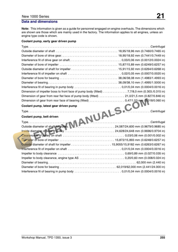
- 2.1.1.13.15. Data and dimensions
- 2.1.1.14. Chapter 22 Flywheel and housing
- 2.1.1.14.1. General description
- 2.1.1.14.2. Flywheel
- 2.1.1.14.3. Ring gear
- 2.1.1.14.4. Flywheel housing
- 2.1.1.14.5. Data and dimensions
- 2.1.1.15. Chapter 23 Electrical equipment
- 2.1.1.15.1. Alternators
- 2.1.1.15.2. General description
- 2.1.1.15.3. Precautions
- 2.1.1.15.4. Drive belts
- 2.1.1.15.5. Alternator
- 2.1.1.15.6. Fault diagnosis
- 2.1.1.15.7. Data and dimensions
- 2.1.1.15.8. Starter motors
- 2.1.1.15.9. General description
- 2.1.1.15.10. Starter motor
- 2.1.1.15.11. Data and dimensions
- 2.1.1.15.12. Starting aid
- 2.1.1.15.13. General description
- 2.1.1.15.14. Starting aid
- 2.1.1.15.15. Data and dimensions
- 2.1.1.16. Chapter 24 Auxiliary equipment
- 2.1.1.16.1. Compressors
- 2.1.1.16.2. General description
- 2.1.1.16.3. Operation
- 2.1.1.16.4. Bendix Compressors
- 2.1.1.16.5. Data and dimensions
- 2.1.1.16.6. Power steering pump
- 2.1.1.16.7. Adaptor for a hydraulic pump or a steering pump with a splined drive
- 2.1.1.16.8. Exhauster
- 2.1.1.17. Chapter 25 Special tools
- 2.1.1.17.1. List of special tools
- 3. GROUP_30_547842EN
- 3.1. GROUP 30
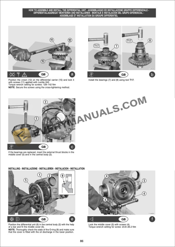
- 3.1.1. DISASSEMBLY OF THE AXLE ASSEMBLY 212
- 3.1.2. DISMANTLING DROP BOX TYPE 357
- 4. GROUP_70_547842EN
- 4.1. GROUP 70
- 4.1.1. DISMANTLING THE MAIN HYDRAULIC PUMP
- 4.1.2. DISMANTLING THE MAIN HYDRAULIC PUMP
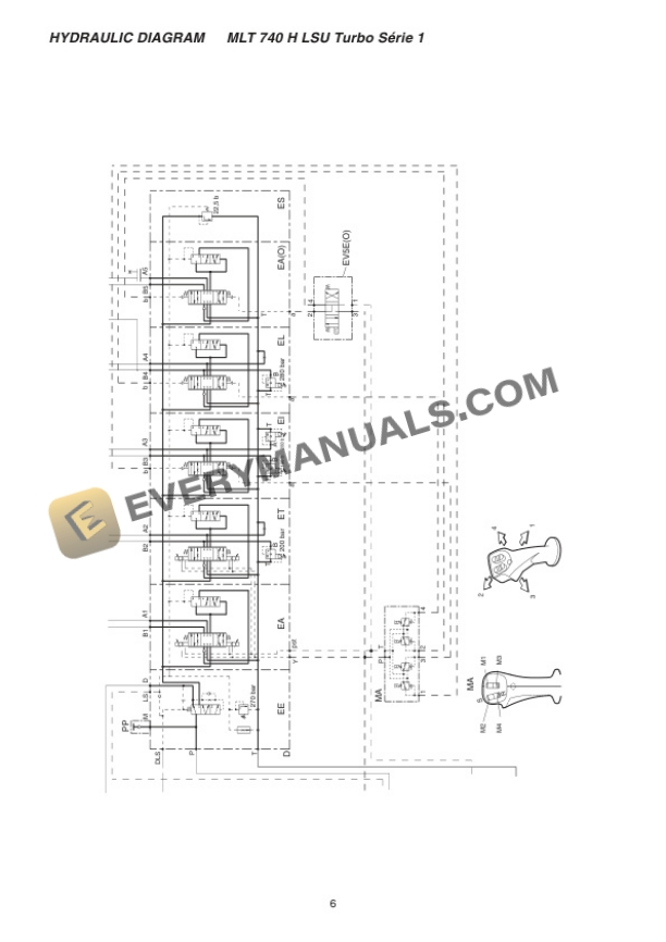
- 4.1.3. HYDRAULIC DIAGRAM
- 5. GROUP_75_547842EN
- 5.1. GROUP 75
- 5.1.1. PUMP DISASSEMBLY A4 VG 71180
- 5.1.2. HYDROSTATIC MOTOR DISASSEMBLY
- 5.1.3. WORKING (ADJUSTING) TRANSMISSION
- 6. GROUP_80_547842EN