Description
-
Model List:
- Type 111 Axle
- 1. Contents
- 2. Introduction
- 2.1. Version tracking
- 2.2. Manual applicability and supported models
- 3. Specifications
- 3.1. Definition of viewpoints
- 3.2. Data plate
- 3.3. Conversion tables
- 3.3.1. Units of pressure
- 3.3.2. Units of weight
- 3.3.3. Units of torque
- 3.4. Torque specifications
- 3.4.1. Coarse pitch
- 3.4.2. Fine pitch
- 3.4.3. Wheel nut tightening torques
- 4. Maintenance
- 4.1. Maintenance points
- 4.2. Oil draining mandatory procedure
- 4.2.1. Central housing
- 4.2.2. Planetary gear reduction
- 4.3. Endstop plier setting
- 4.3.1. Retaining snap ring for bores
- 4.3.2. Retaining snap ring for shafts
- 4.4. Input seal greasing
- 4.4.1. Handling instruction greasing 1
- 4.4.2. Handling instruction greasing 2
- 4.5. Maintenance intervals
- 4.6. Lubricant sealant specifications
- 5. Safety precautions
- 6. Planetary reduction (flanged nuts version)
- 7. Manual emergency release
- 7.1. Exploded view
- 7.2. Manual emergency release
- 8. Adjustment after manual release
- 8.1. Exploded view
- 8.2. Adjustment after manual release
- 9. Brake wear check procedure
- 9.1. Exploded view
- 9.2. Brake wear check procedure
- 9.3. Special tools
- 10. Service and negative brake
- 11. Service and sahr incoming disc brake
- 11.1. Exploded view
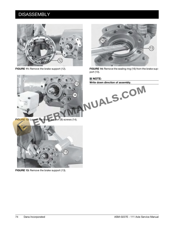
- 11.2. Disassembly
- 11.3. Assembly
- 11.4. Checking wear and replacing the braking pads
- 11.5. Caliper assembly and setting
- 12. Incoming drum brake
- 13. Normal differential
- 13.1. Exploded view
- 13.2. Disassembly
- 13.3. Assembly
- 14. Limited slip differential unit 45
- 14.1. Exploded view
- 14.2. Disassembly
- 14.3. Assembly
- 15. Bevel pinion normal flange and nut revolution counter version
- 15.1. Exploded view
- 15.2. Disassembly
- 15.3. Assembly
- 15.4. Normal flange version
- 15.5. Revolution counter version
- 16. Ring and pinion adjusting version pinion integral and double arm
- 16.1. Exploded view
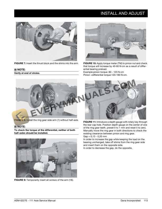
- 16.2. Install and adjust
- 17. Flanged reduction gear 603 type integral 603 input gear
- 18. Bevel pinion flanged to reduction gear 603
- 19. Separate pinion cover for flanged gearbox
- 19.1. Exploded view
- 19.2. Disassembly
- 19.3. Assembly
- 19.3.1. Calculating pinion bearings rolling torque
- 19.3.2. Calculating pinion center distance
- 20. United pinion cover for flanged gearbox
- 20.1. Exploded view
- 20.2. Disassembly
- 20.3. Assembly
- 20.3.1. Calculating pinion center distance
- 20.3.2. Calculating pinion bearings rolling torque
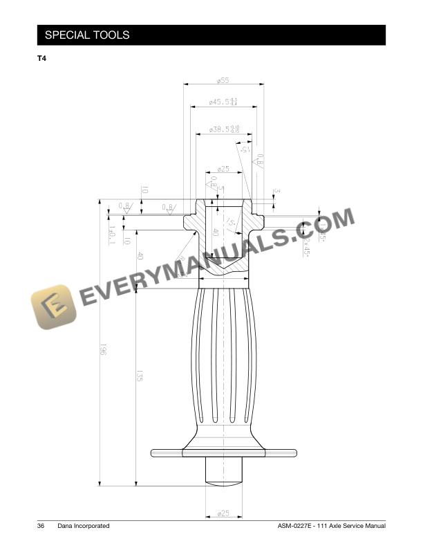
- 20.4. Special tools
- 21. Flanged reduction gear 315 type integral input gear (din flange)
- 21.1. Exploded view
- 21.2. Disassembly
- 21.3. Assembly
- 22. Flanged reduction gear 315 type interchangable input gear (end yoke flange)
- 23. Differential with block to spheres 100 (last version)
- 23.1. Exploded view
- 23.2. Disassembly
- 23.3. Assembly
- 24. Counter revolution sensor (dropin type)
- 24.1. Exploded view
- 24.2. Disassembly
- 24.3. Assembly
- 25. MR 647431 EN 202205.pdf
- 25.1. Page de garde / Front page