Description
-
Model List:
- 140A Auger Platform
- 160A Auger Platform
- 180A Auger Platform
- 1160A Auger Platform
- 1180A Auger Platform
- 1. Introduction
- 1.1. Foreword
- 1.2. Recognize Safety Information
- 1.3. Understand Signal Words
- 1.4. Follow Safety Instructions
- 1.5. Spanish Safety Signs and Operators Manual
- 1.6. Maintain a Safety Area Around the Machine
- 1.7. Operate Safely
- 1.8. Keep Riders Off Machine
- 1.9. Towing the Machine on Public Roads
- 1.10. Tow Loads Safely
- 1.11. Observe Maximum Transport Speed
- 1.12. Prepare for Emergencies
- 1.13. Fire Prevention
- 1.14. Fire Prevention
- 1.15. In Case of Fire
- 1.16. Wear Protective Clothing
- 1.17. Protect Against Noise
- 1.18. Handle Chemical Products Safely
- 1.19. Service Machines Safely
- 1.20. Practice Safe Service Procedures
- 1.21. Check Machine Safety
- 1.22. Stay Clear of Rotating Drivelines
- 1.23. Avoid Injury from Thrown Objects
- 1.24. Use Safety Lights and Devices
- 1.25. Practice Safe Maintenance
- 1.26. Support Machine Properly
- 1.27. Remove Paint Before Welding or Heating
- 1.28. Avoid Heating Near Pressurized Fluid Lines
- 1.29. Avoid HighPressure Fluids
- 1.30. Avoid HighPressure Jet on Safety Decals
- 1.31. Decommissioning Proper Recycling and Disposal of Fluids and Components
- 2. Safety Signs
- 2.1. Replace Safety Signs
- 2.2. Safety Decal Locations
- 2.2.1. General
- 2.2.2. Safety Decals
- 3. Identification View
- 3.1. Identification View
- 4. Attach and Detach (140A, 160A, and 180A Platforms)
- 4.1. Attach Platform to Windrower
- 4.2. Platform Flotation and Adjustment
- 4.2.1. Platform Float Operating Guidelines
- 4.2.2. Platform Float Adjustment
- 4.2.3. Platform Float Options
- 4.2.4. Leveling
- 4.2.5. Platform Drive
- 4.2.6. Platform Angle
- 4.3. Attach Hydraulics to W110 Windrower
- 4.4. Attach Hydraulics to W150 Windrower
- 4.5. Install Reverser Valve Jumper Hose
- 4.6. Detach Hydraulics from Windrower
- 5. Attach and Detach (1160A and 1180A Platforms)
- 5.1. Attach Platform to Windrower
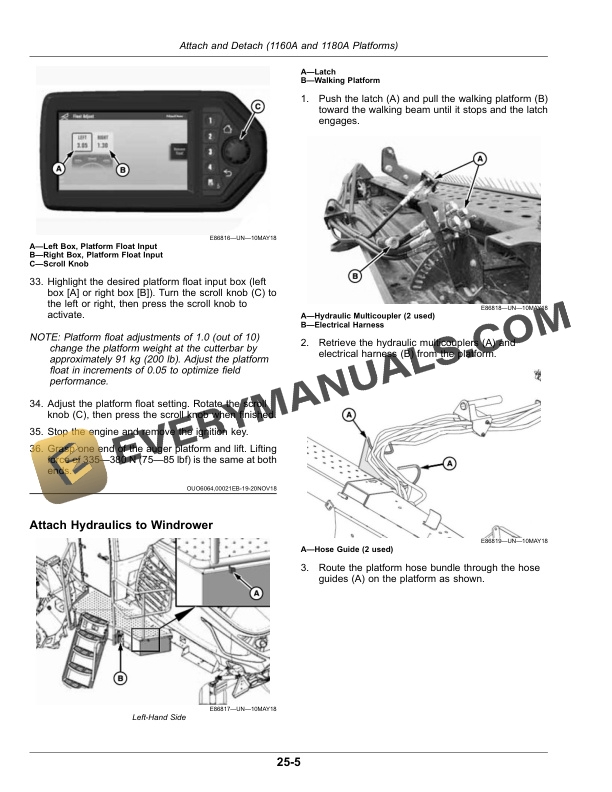
- 5.2. Attach Hydraulics to Windrower
- 5.3. Detach Hydraulics from Windrower
- 5.4. Detach Platform from Windrower
- 5.5. Platform Flotation and Adjustment
- 5.5.1. Platform Float Operating Guidelines
- 5.5.2. Check Platform Float
- 5.5.3. Set Platform Float
- 5.5.4. Remove and Restore Platform Float
- 6. Operate Platform
- 6.1. BreakIn Inspection
- 6.2. Preseason Check
- 6.3. Daily Startup Check
- 6.4. Shutdown Procedure
- 6.5. Open and Close Drive Shields and Driveline Shields
- 6.6. Change Amber Reflector Assembly for EngineForward or CabForward Transport
- 6.7. Lift Cylinder Lockouts
- 6.8. Unplug Conditioner
- 6.9. Unplug Knife
- 6.10. Platform Operation
- 6.11. Lean Bar Position
- 6.12. Auger Speed
- 6.13. Reel Speed
- 6.14. Auger Position
- 6.14.1. Auger Fore/Aft Adjustment
- 6.14.2. Auger Vertical Adjustment
- 6.15. Reel Position
- 6.15.1. Reel Fore/Aft Position
- 6.15.2. Reel Vertical Position
- 6.16. Tine Aggressiveness Adjustment
- 6.17. Cutting Height
- 6.18. Platform Angle
- 6.19. Platform Flotation
- 6.20. Feed Pan and RockDrop Tine Position
- 6.21. Hay Conditioner
- 6.21.1. Conditioner Roll Gap Adjustment
- 6.21.2. Conditioner Roll Timing
- 6.21.3. Conditioner Roll Alignment
- 6.22. Conditioner Roll Tension
- 6.23. Forming Shields
- 6.23.1. Adjust Side Deflectors
- 6.23.2. Rear Deflector
- 6.24. Tall Crop Dividers
- 6.24.1. Adjust Tall Crop Dividers
- 6.24.2. Remove Tall Crop Dividers
- 6.25. Ground Speed
- 6.26. Grass Seed Windrowing
- 6.26.1. Stub Guards and HoldDowns
- 6.26.2. Special Auger Design
- 6.26.3. Seventh Bat Reel
- 6.26.4. Auger Pan Extensions
- 6.26.5. Windrow Forming Rods
- 7. Hay Tips
- 7.1. Topsoil Moisture
- 7.2. Weather and Topography
- 7.3. Windrow Characteristics
- 7.4. Driving on Windrow
- 7.5. Raking and Tedding
- 7.6. Chemical Drying Agents
- 8. Attachments
- 8.1. Additional Skid Shoes
- 8.2. Gauge Roller Kit
- 8.3. Replacement Reel Bat Kits 140A, 160A, and 1160A Auger Platforms
- 8.4. Guard Conversion Kit
- 8.5. Tall Crop Divider Kit
- 9. Lubrication and Maintenance
- 9.1. Lubricate and Maintain Machine Safely
- 9.2. Observe Service Intervals
- 9.3. Recommended Lubricants
- 9.4. Alternative and Synthetic Lubricants
- 9.5. Mixing of Lubricants
- 9.6. Lubricant Storage
- 9.7. Perform Lubrication and Maintenance
- 9.8. After First 10 Hours
- 9.9. Every 10 Hours or Daily
- 9.10. Every 25 Hours
- 9.11. After First 50 Hours
- 9.12. Every 50 Hours
- 9.13. Every 100 Hours
- 9.13.1. Check Knife Drive Gear Case/Conditioner Drive Gear Case Oil Level
- 9.13.2. Check Knife Drive Gear Case Mounting Bolt Torque
- 9.14. Every 1000 Hours or Three Years
- 9.14.1. Knife Drive Gear Case
- 9.14.2. Conditioner Drive Gear Case
- 9.15. Every Six Years Hydraulic Hoses
- 10. Troubleshoot
- 10.1. Windrower Performance
- 10.2. Mechanical
- 11. Service
- 11.1. Hydraulics
- 11.2. Remove and Install Knife Section
- 11.3. Remove and Install Cutterbar
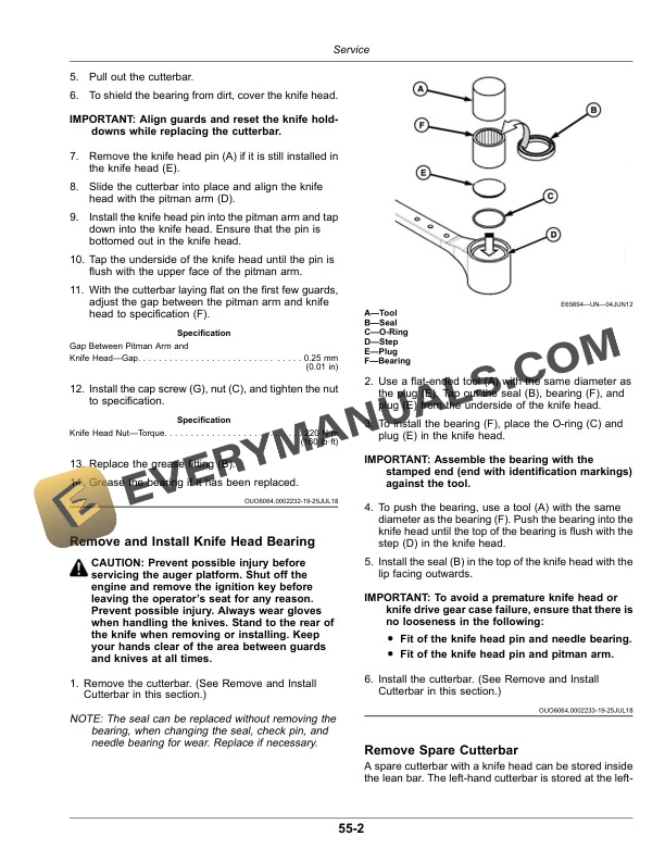
- 11.4. Remove and Install Knife Head Bearing
- 11.5. Remove Spare Cutterbar
- 11.6. Adjust Knife Guards
- 11.7. Replace Knife Pointed Guards
- 11.8. Replace Knife Stub Guards
- 11.9. Adjust Knife HoldDowns Pointed Guards
- 11.10. Adjust Knife HoldDowns Stub Guards
- 11.11. Remove and Install Knife Drive Timing Belts
- 11.12. Adjust Knife Drive Timing Belts
- 11.13. Adjust Knife Drive Timing
- 11.14. Reel and Reel Drive
- 11.15. Sealed Bearing Installation
- 11.16. Remove and Install Reel Tines and Tine Bar Bearings
- 11.16.1. Tines and BearingsCam End
- 11.16.2. Tines and Bearings Center Section
- 11.16.3. Tines and Bearings Opposite Cam
- 11.16.4. Tine Replacement Tine Bar Extension
- 11.17. Repair Auger Pans
- 11.18. Remove and Install Rubber Fingers
- 11.19. Remove and Install Stripper Bars
- 11.20. Adjust Stripper Bars
- 11.21. Install Front Stripper Bar Extensions
- 11.22. Auger and Auger Drive
- 11.23. Remove and Install Forming Shield
- 11.23.1. Remove Forming Shield
- 11.23.2. Disassemble Forming Shield
- 11.23.3. Install Forming Shield
- 11.24. Condition Motor and Condition Drive Gear Case
- 11.25. Replace Skid Shoe Wear Plate
- 11.26. Remove and Install Gauge Rollers
- 11.26.1. Install
- 11.27. Electrical
- 11.28. Interval Maintenance
- 11.29. Maintenance Record
- 12. Storage
- 12.1. Store Auger PlatformEnd of Season
- 12.2. Remove Auger Platform from StorageBeginning of Season
- 13. Specifications
- 13.1. SelfPropelled Platform
- 13.2. SAE Face Seal Fitting Torque ChartStandard Pressure Applications
- 13.3. SAE Face Seal Fitting Torque ChartHigh Pressure Applications
- 13.4. Unified Inch Bolt and Screw Torque Values
- 13.5. Metric Bolt and Screw Torque Values
- 13.6. Conversion Chart
- 13.7. Face Seal Fittings Assembly and InstallationAll Pressure Applications
- 13.7.1. Face Seal ORing to Stud End Installation
- 13.7.2. Face Seal Adjustable Stud End ORing Installation
- 13.7.3. Face Seal Straight Stud End ORing Installation
- 13.7.4. Fitting Installation
- 13.7.5. Assembly Torque
- 14. Serial Numbers
- 14.1. Serial Number Plate
- 14.2. Record Auger Platform Serial Number
- 14.3. Keep Proof of Ownership
- 14.4. Keep Machines Secure
- 15. John Deere Service Keeps You On The Job
- 15.1. Technical Information
- 15.2. John Deere Is At Your Service