Description
-
Model List:
- 2100 Minimum Till Ripper
- 1. Contents
- 1.0.1. Recognize Safety Information
- 1.0.2. Understand Signal Words
- 1.0.3. Follow Safety Instructions
- 1.0.4. Operate Safely
- 1.0.5. Keep Riders Off Machine
- 1.0.6. Prepare for Emergencies
- 1.0.7. Wear Protective Clothing
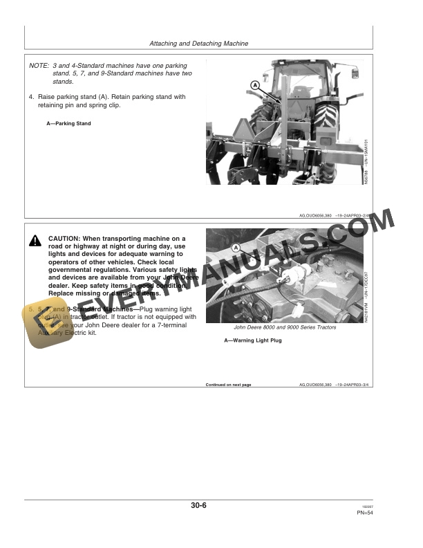
- 1.0.8. Use Safety Lights and Devices
- 1.0.9. Use a Safety Chain
- 1.0.10. Observe Maximum Transport Speed
- 1.0.11. Transport Safely
- 1.0.12. Tow Loads Safely
- 1.0.13. Service Machine Safely
- 1.0.14. Practice Safe Maintenance
- 1.0.15. Support Raised Machine
- 1.0.16. Avoid HighPressure Fluids
- 1.0.17. Check Hydraulic Hoses
- 1.0.18. Service Tires Safely
- 1.0.19. Avoid Power Lines
- 1.0.20. Store Attachments Safely
- 1.1. Safety Signs
- 1.1.1. Replace Damaged or Missing Safety Signs
- 1.1.2. Safety Signs
- 1.2. Safety Features
- 1.2.1. Safety Features
- 1.3. Preparing Tractor
- 1.3.1. Using Your Tractor Operators Manual
- 1.3.2. Determining Tractor Requirements
- 1.3.3. Drawbar Requirements
- 1.3.4. Preparing Hydraulic System
- 1.3.5. Preparing Power TakeOff
- 1.3.6. Adjusting Tractor Wheel Spacing
- 1.3.7. Tightening Tractor Hitch Hammer Strap Hardware
- 1.3.8. Positioning DrawbarDrawn
- 1.3.9. Using a Safety ChainDrawn
- 1.3.10. Raising and Locking 3Point HitchDrawn
- 1.3.11. Positioning DrawbarIntegral
- 1.3.12. Positioning Sway BlocksIntegral
- 1.3.13. Adjusting 3Point HitchIntegral
- 1.3.14. Determining Rear Wheel WeightingIntegral
- 1.3.15. Adding Front Ballast, FourWheel Drive Tractors and Tracdrive TractorsIntegral
- 1.3.16. Adding Front Ballast, TwoWheel Drive and MFWD TractorsIntegral
- 1.3.17. Determining Front BallastIntegral
- 1.3.18. Implement Code TablesIntegral
- 1.4. Preparing Machine
- 1.4.1. Checking and Lubricating Machine
- 1.4.2. Preparing Machine Checklist
- 1.4.3. Drawbar Requirements
- 1.4.4. Checking Tire Pressure
- 1.4.5. Checking Depth Control Wheel Bolts and BearingsDrawn
- 1.4.6. Tightening Hardware
- 1.4.7. Tightening Hitch Link Hardware
- 1.4.8. Tightening Coulter Hardware
- 1.4.9. Leveling Main Frame, SidetoSideIntegral
- 1.4.10. Leveling Main Frame, FronttoRearIntegral
- 1.4.11. Leveling Main Frame, FronttoRearDrawn
- 1.4.12. Changing Size and Standard Spacing
- 1.5. Attaching and Detaching Machine
- 1.5.1. Attaching Machine Safely
- 1.5.2. Making Proper Hose Connections
- 1.5.3. Setting Rockshaft Selector LeverIntegral
- 1.5.4. Using External Raise/Lower Rockshaft SwitchesIntegral
- 1.5.5. Attaching Machine to TractorIntegral
- 1.5.6. Attaching Machine to TractorDrawn
- 1.5.7. Checking Depth Control Wheel OperationDrawn
- 1.5.8. Checking WingFold Operation9Standard Machine
- 1.5.9. Detaching Machine from TractorIntegral
- 1.5.10. Detaching Machine from TractorDrawn
- 1.6. Transporting
- 1.6.1. Transport Safely
- 1.6.2. Keeping Riders Off Machine
- 1.6.3. Transporting MachineIntegral
- 1.6.4. Attaching Safety Chain to TractorDrawn
- 1.6.5. Positioning DrawbarDrawn
- 1.6.6. Positioning Jack for TransportDrawn
- 1.6.7. Transporting MachineDrawn
- 1.7. Operating Machine
- 1.7.1. Keeping Riders Off Machine
- 1.7.2. Following Safe Operating Procedures
- 1.7.3. Guidelines for Use
- 1.7.4. Using Operators Manual Holder
- 1.7.5. Tightening Hardware
- 1.7.6. Tightening Hitch Link Hardware
- 1.7.7. Tightening Coulter Hardware
- 1.7.8. Leveling Main Frame, SidetoSideIntegral
- 1.7.9. Leveling Main Frame, FronttoRearIntegral
- 1.7.10. Leveling Main Frame, FronttoRearDrawn
- 1.7.11. Using Depth Control, John Deere 7000, 8000, and 9000 Series TractorsIntegral
- 1.7.12. Using Draft Control, Tractor with Electronic HitchIntegral
- 1.7.13. Setting Depth ControlDrawn
- 1.7.14. Using Implement Management SystemIf Equipped
- 1.7.15. Adjusting Stabilizer WheelsIf Equipped
- 1.7.16. Using Standards
- 1.7.17. Resetting Standards
- 1.7.18. Using Coulters
- 1.7.19. Adjusting Spring Cushion Coulters
- 1.7.20. Adjusting Closing WheelsIf Equipped
- 1.7.21. Adjusting Closing Wheels Down PressureIf Equipped
- 1.7.22. Removing Closing WheelsIf Equipped
- 1.7.23. Soil CompactionSymptoms
- 1.7.24. Soil CompactionDetecting with John Deere Soil Probe
- 1.7.25. Soil CompactionQuestions and Answers
- 1.8. Attachments
- 1.8.1. Setback Bars
- 1.8.2. Closing Wheels
- 1.8.3. Drawn Hitch
- 1.8.4. Stabilizer Wheels Inline with Coulters on Frame Extensions7 and 9Standard Rigid Machines
- 1.9. Lubrication and Maintenance
- 1.9.1. Lubricating and Maintaining Machine Safely
- 1.9.2. Alternative and Synthetic Lubricants
- 1.9.3. Lubricant Storage
- 1.9.4. Lubrication Symbols
- 1.9.5. Lubrication Intervals
- 1.9.6. Grease Depth Control Wheel BearingsDrawn
- 1.9.7. Repacking Stabilizer Wheel Bearings
- 1.9.8. Repacking Coulter Bearings
- 1.10. Troubleshooting
- 1.10.1. Troubleshooting
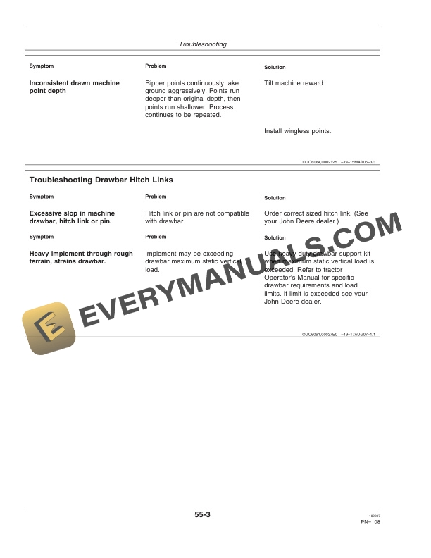
- 1.10.2. Troubleshooting Drawbar Hitch Links
- 1.10.3. Drawn Machine Chatters When Lowering
- 1.11. Service
- 1.11.1. Practice Safe Maintenance
- 1.11.2. Using Safe Service Procedures
- 1.11.3. Work in Clean Area
- 1.11.4. Service Machines Safely
- 1.11.5. Illuminate Work Area Safely
- 1.11.6. Support Machine Properly
- 1.11.7. Replacing Ground Engaging Tools
- 1.11.8. Keep Service Area Clean
- 1.11.9. Metric Bolt and Screw Torque Values
- 1.11.10. Unified Inch Bolt and Cap Screw Torque Values
- 1.11.11. ORing Boss Fitting Torque Chart
- 1.11.12. Discarded Tires
- 1.11.13. Service Tires Safely
- 1.11.14. Repair Tire
- 1.11.15. Checking Tire Pressure
- 1.11.16. Tightening Tractor Hitch Hammer Strap Hardware
- 1.11.17. Tightening Hitch Link Hardware
- 1.11.18. Tightening Coulter Hardware
- 1.11.19. Checking Depth Control and Stabilizer Wheel Bolts and BearingsDrawn
- 1.11.20. Retightening Standard and Setback Bar Lock Nuts
- 1.11.21. Replacing Shear BoltsStandards
- 1.11.22. Replacing Wear Shin19 mm (3/4 in.) Standards
- 1.11.23. Replacing Wear Shins32 mm (11/4 in.) Standards
- 1.11.24. Replacing Ripper Points19 mm (3/4 in.) Standards
- 1.11.25. Replacing Ripper Points32 mm (11/4 in.) Standards
- 1.11.26. Replacing Cast EXTREME LASERRIP Ripper Points
- 1.11.27. MinTill Ripper Points19 mm (3/4 in.) Standards
- 1.11.28. MinTill Ripper Point Comparisons19 mm (3/4 in.) Standards
- 1.11.29. Optional Ripper Points32 mm (11/4 in.) Standards
- 1.11.30. Servicing Coulter Bearings
- 1.11.31. Checking Depth Control Hydraulic SystemDrawn
- 1.11.32. Preventing Hydraulic System ContaminationFolding and Drawn
- 1.11.33. Removing CylindersFolding and Drawn
- 1.11.34. Installing and Bleeding Cylinders
- 1.11.35. Preparing for Storage
- 1.12. Specifications
- 1.12.1. Hitch Specifications
- 1.12.2. Tractor Size Recommendations
- 1.12.3. Hydraulic System Requirements
- 1.12.4. Tractor 3Point Hitch Requirements
- 1.12.5. Machine Specifications
- 1.12.6. Download Force On Tractor Drawbar
- 1.12.7. Product Identification Number
- 1.13. John Deere Service Literature Available
- 1.13.1. Technical Information
- 1.14. John Deere Service Keeps You On The Job
- 1.14.1. John Deere Is At Your Service
- 2. Page Numbers
- 2.1. Section 05