Description
-
Model List:
- 455 Grain Drill
- 1. Introduction
- 1.1. Foreword
- 1.2. A Message to Our Customers
- 1.3. Grain Drill
- 1.4. Recognize Safety Information
- 1.5. Understand Signal Words
- 1.6. Follow Safety Instructions
- 1.7. Replace Safety Signs
- 1.8. Hydraulic Hose Replacement
- 1.9. Prevent Machine Runaway
- 1.10. Keep Riders Off Machine
- 1.11. Prepare for Emergencies
- 1.12. Wear Protective Clothing
- 1.13. Handle Agricultural Chemicals Safely
- 1.14. Use Safety Lights and Devices
- 1.15. Use a Safety Chain
- 1.16. Avoid Tipovers
- 1.17. Follow Tire Recommendations
- 1.18. Operator Ability
- 1.19. Operate Safely
- 1.20. Transport Safely
- 1.21. Tow Loads Safely
- 1.22. Observe Maximum Transport Speed
- 1.23. Remove Paint Before Welding or Heating
- 1.24. Avoid Heating Near Pressurized Fluid Lines
- 1.25. Practice Safe Maintenance
- 1.26. Avoid HighPressure Fluids
- 1.27. Store Attachments Safely
- 1.28. Decommissioning Proper Recycling and Disposal of Fluids and Components
- 1.29. Safety FeaturesTwoUnit Drill
- 1.30. Safety FeaturesThreeUnit Drill
- 2. Safety Signs
- 2.1. Sudden Hitch Movement
- 2.2. Transport Guidelines
- 2.3. Hydraulic Injection
- 2.4. Tow Safely
- 2.5. Falling from Height
- 2.6. Sudden Crushing Movement
- 2.7. Sudden Crushing Movement
- 2.8. Avoid Runover
- 2.9. Sudden Crushing Movement
- 2.10. Chemical Contact
- 2.11. Falling from Height
- 3. Information Decals
- 3.1. Information Decals
- 4. Preparing the Tractor
- 4.1. Use the Tractor Operators Manual
- 4.2. Adjust Metering ValvesTractors with Mechanical SCV
- 4.3. Adjust Metering ValvesTractors with Electro/Hydraulic SCV Controls
- 4.4. Check Seed MonitorIf Equipped
- 4.5. ImplementTractor Compatibility
- 4.6. Prepare the Hitch
- 4.7. Install Regular Drawbar Support (5560 Series Tractors)
- 4.8. Install WideSwing Drawbar Support (5560 Series Tractors)
- 4.9. Attach Drawbar Support on 7000 Series Tractors
- 4.10. Safety Chain
- 4.11. Lever Lock ClipTractors with Mechanical SCV Controls
- 4.12. Install Lever Lock ClipTractors with Mechanical SCV Controls
- 5. Preparing the Machine
- 5.1. Check Tire Pressure
- 5.2. Calibrate Drill
- 5.3. Tighten Wheel Bolts
- 5.4. Lubricate Grain Drill
- 6. Attaching and Detaching
- 6.1. Attach Implement to the Tractor
- 6.2. Detach the Implement from the Tractor
- 6.2.1. Detaching from a Folded Implement
- 6.2.2. Detaching from an Unfolded Implement
- 7. Transporting
- 7.1. Transporting
- 7.2. Warning Light Configuration (Style A)
- 7.3. Light Enhancement Module
- 8. Operating the Machine
- 8.1. Guidelines for Use
- 8.2. Check Seed MonitorIf Equipped
- 8.3. Level Implement
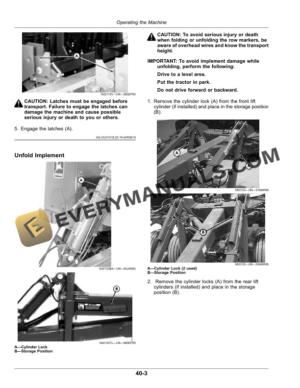
- 8.4. Fold Implement
- 8.5. Unfold Implement
- 8.6. Adjust Hydraulic Downforce (Tractors with Closed Center Hydraulic Systems)
- 8.7. Adjust Hydraulic Downforce (Tractors with Open Center Hydraulic Systems)
- 8.8. Adjust Depth Gauging Press Wheels
- 8.9. Adjust Depth Gauging Press Wheel Handle
- 8.10. Operate Select LiftIf Equipped
- 8.11. Use Lever Lock Clip
- 8.12. Adjust DoubleDisk Outside Scrapers
- 8.13. Check Disk BladesAluminum Boot
- 8.14. Set Spill Shields
- 8.15. Change Partition
- 8.16. Change Partition Position
- 8.17. Change to 40 Grain and 60 Fertilizer Partition Position
- 8.18. Importance of Checking Quantities Drilled
- 8.19. Checking Quantities DrilledMethod 1
- 8.20. Checking Quantities DrilledMethod 2
- 8.21. Drilling Row Crops
- 9. Operating the FlutedFeed Meter
- 9.1. Inspect Grain Feeds
- 9.2. Set Grain Shifter
- 9.3. Using Seed Mixtures
- 9.4. Cleaning and Setting
- 9.5. Using Half Speed Drive Attachment
- 9.6. Understand Rate Charts
- 9.7. Using Kilograms of Seed Per Hectare Chart
- 9.8. Using Pounds of Seed Per Acre Chart
- 9.9. Use Density Meter and Seed Charts
- 9.10. Grain Seed Rate Chart15 cm Rows
- 9.11. Grain Seed Rate Chart6 Inch Rows
- 9.12. Grain Seed Rate Chart19 cm Rows
- 9.13. Grain Seed Rate Chart7.5 Inch Rows
- 9.14. Grain Seed Rate Chart25 cm Rows
- 9.15. Grain Seed Rate Chart10 Inch Rows
- 10. Operating the Fertilizer Meter
- 10.1. Fertilizer Feed Shaft Speed
- 10.2. Fertilizer Drive Settings
- 10.3. Use Density Meter and Fertilizer Charts
- 10.4. Fertilizer Charts
- 10.5. Clean the Fertilizer Box
- 11. Operating the Grass Seed Meter
- 11.1. Half Speed Grass Drive (If Equipped)
- 11.2. Checking Feeds
- 11.3. Set Feed Shifter
- 11.4. Use Seed Mixtures
- 11.5. Use Seed Charts
- 11.6. Use Density Meter and Grass Seed Charts
- 11.7. Grass Seed Rate Chart15 cm Rows
- 11.8. Grass Seed Rate Chart6 Inch Rows
- 11.9. Grass Seed Rate Chart19 cm Rows
- 11.10. Grass Seed Rate Chart7.5 Inch Rows
- 11.11. Grass Seed Rate Chart25 cm Rows
- 11.12. Grass Seed Rate Chart10 Inch Rows
- 12. Attachments
- 12.1. Select Lift
- 12.2. Grass Seed Attachment
- 12.3. HalfRate Drive for Grass Seed Attachment
- 12.4. Seed Agitator
- 12.5. Drillshaft Turn Indicator
- 12.6. HalfSpeed Drive for FlutedFeed
- 12.7. Grain Feed StopFluted Feeds
- 12.8. Fertilizer Feed Stop
- 12.9. Grass Seed Feed Stop
- 12.10. Install Press Wheels
- 12.11. Dual Press Wheel Placement 19 cm (7.5 in) and 25 cm (10 in) Row Spacing
- 12.12. Attach Marker Disk to Marker Arm
- 12.13. Additional Selector Valve for Two Outlet Tractor Systems
- 12.14. Row Marker Sequencer Control
- 12.15. Row Marker Selector Valve
- 13. Lubrication and Maintenance
- 13.1. Multipurpose Extreme Pressure (EP) Grease
- 13.2. Gear Oil
- 13.3. Alternative and Synthetic Lubricants
- 13.4. Lubrication Symbols
- 13.5. Lubricant Storage
- 13.6. Lubrication
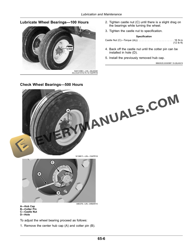
- 13.7. Lubricate Wheel Bearings100 Hours
- 13.8. Check Wheel Bearings500 Hours
- 14. Troubleshooting
- 14.1. TroubleshootingGeneral
- 14.2. TroubleshootingHydraulic Downforce
- 14.3. TroubleshootingHydraulic Downforce on Tractors with Open Center Hydraulics (Using Attachment for Field Conversion)
- 15. Servicing
- 15.1. Practice Safe Maintenance
- 15.2. Prevent Machine Runaway
- 15.3. Handle Agricultural Chemicals Safely
- 15.4. LockUp Rockshafts and Openers
- 15.5. Metric Bolt and Screw Torque Values
- 15.6. Unified Inch Bolt and Screw Torque Values
- 15.7. Service Tires Safely
- 15.8. Check Tire Pressure
- 15.9. Check Wheel Bolts
- 15.10. Check Wheel Bearings
- 15.11. Secure Machine for Safe Servicing
- 15.12. Hydraulic Hose Replacement
- 15.13. Remove and Repair Cylinders
- 15.14. Bleed Trapped Air from Cylinders
- 15.15. Reset FlutedFeed Cups
- 15.16. Check Feed Shaft Rolling Torque
- 15.17. Tighten Fertilizer Feed Shaft Drive Chains
- 15.18. Tighten Fertilizer Drive Chains
- 15.19. Replace Fertilizer Feed Wheels
- 15.20. Determine When to Replace DoubleDisk Blades
- 15.21. Reverse DoubleDisk Blades to Maintain Offset
- 15.22. Replace and Adjust DoubleDisk Blades on Aluminum Boots
- 15.23. Replace Inside Scrapers
- 15.24. Replace Seed TubesDoubleDisk Opener
- 15.25. Replace Single Wheel Wing Drive Shear Pin
- 15.26. Hydraulic DiagramOpener Lift Cylinders 7.6 m (25 ft)
- 15.27. Hydraulic DiagramOpener Lift Cylinders 9.1 m (30 ft)
- 15.28. Hydraulic DiagramOpener Lift Cylinders 10.7 m (35 ft)
- 15.29. Hydraulic DiagramCart Lift Cylinders 7.6 m (25 ft)
- 15.30. Hydraulic DiagramCart Lift Cylinders 9.1 m and 10.7 m (30 and 35 ft)
- 15.31. Hydraulic DiagramWing Fold Cylinders
- 15.32. Hydraulic DiagramSelector Valve (Two Outlet Conversion)
- 15.33. Hydraulic DiagramSingle Row Markers (LeftHand)
- 15.34. Hydraulic DiagramLeftHand and RightHand Dual Row Markers
- 16. Storing
- 16.1. Prepare Drill for Storage
- 16.2. Remove Drill from Storage
- 17. Specifications
- 17.1. Tractor Requirements
- 17.2. Drawbar Hitch Loads
- 17.3. Specifications
- 17.4. Locate and Record Your Drill Identification Number
- 17.5. Keep Proof of Ownership
- 17.6. Keep Machines Secure
- 18. John Deere Service Literature
- 18.1. Technical Information
- 19. John Deere Service Keeps You on the Job
- 19.1. John Deere Is At Your Service