Description
-
Model List:
- SeedStar 2 Monitor
- 1. Contents
- 1.1. Identification Views
- 1.1.1. Identification Views
- 1.1.2. Recognize Safety Information
- 1.1.3. Understand Signal Words
- 1.1.4. Follow Safety Instructions
- 1.1.5. Prevent Machine Runaway
- 1.1.6. Avoid HighPressure Fluids
- 1.1.7. Prepare for Emergencies
- 1.1.8. Electrical Connections
- 1.1.9. Prevent Battery Explosions
- 1.1.10. Do Not Modify Monitor or Radar Sensor
- 1.2. Safety Signs
- 1.2.1. Safety Signs
- 1.3. How to Use Monitor
- 1.3.1. Use with GreenStar Monitors
- 1.3.2. Monitor Controls
- 1.3.3. Monitor Power Up and Power Down
- 1.3.4. Standard Buttons
- 1.3.5. Input Entry Methods
- 1.3.6. Screen Layout Manager
- 1.3.7. Screen Navigation
- 1.4. Monitor Settings
- 1.4.1. Configure Brightness, Volume, and Color
- 1.4.2. Configure Language and Units of Measure
- 1.4.3. Configure Date and Time
- 1.4.4. Touchscreen Calibration
- 1.5. Performance Monitor
- 1.5.1. Check Implement Width in Performance Monitor
- 1.5.2. Radar Configuration
- 1.5.3. Radar Calibration
- 1.6. Quick Reference Setup
- 1.6.1. Quick Reference Setup for Ground Driven Machines
- 1.6.2. Quick Reference Setup for VRD Machines
- 1.7. SETUP Basic Planter Configuration
- 1.7.1. Check Current Configuration
- 1.7.2. Configure Planter Drive Source
- 1.7.3. Configure Frame, Split Row, and Drive Disconnect Warning
- 1.7.4. Configure RowCommand
- 1.7.5. Recommended RowCommand Section Configurations
- 1.7.6. Seed Sensors On/Off
- 1.7.7. Vacuum Sensors
- 1.7.8. Vacuum Sensor Calibration
- 1.7.9. Liquid Fertilizer Sensors
- 1.7.10. Liquid Fertilizer Sensor Calibration (Optional)
- 1.7.11. Calibrate Common Start and Stop Height
- 1.7.12. Calibrate Separate Start and Stop Height
- 1.7.13. Ground Speed Source
- 1.8. SETUP VariableRate Drive
- 1.8.1. VariableRate Drive (VRD) Overview
- 1.8.2. Quick Start OverviewVariable Rate Drive
- 1.8.3. Rotate Seed Meters Overview
- 1.8.4. Enable VariableRate Drive Software
- 1.8.5. Check Current Configuration
- 1.8.6. Set Meter Type and Row Unit Drive Type
- 1.8.7. Adjust Motion Sensor GapAll Planters Except 1770NT, 1790, and D
- 1.8.8. Adjust Motion Sensor Gap1770NT, 1790, and Deere/Bauer
- 1.8.9. Adjust Parallel Arm Height Switch
- 1.8.10. Assign MotorRows, Sprockets, and Width Disconnect
- 1.9. SETUP Seed Rates
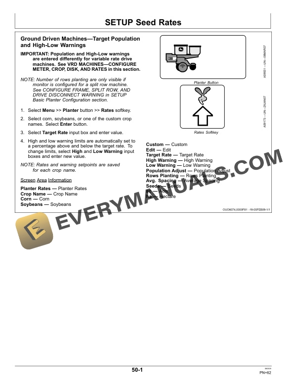
- 1.9.1. Ground Driven MachinesTarget Population and HighLow Warnings
- 1.9.2. VRD MachinesConfigure Meter, Crop, Disk, and Rates
- 1.9.3. Population Adjust (PA)
- 1.10. Main Run Screens
- 1.10.1. Machines with RowCommand
- 1.10.2. Ground Driven Machines
- 1.10.3. VariableRate Drive Machines
- 1.10.4. Half Screen Layout
- 1.10.5. Turning View Warning Suppression
- 1.10.6. Headland Warning Suppression
- 1.10.7. Transport Mode
- 1.11. Counters and Calculators
- 1.11.1. Area Counters, Seeds Per Hour, Seeds Per Area, and Area Until Em
- 1.11.2. Transmission Sprocket Calculator
- 1.11.3. Seed Estimator by Bag
- 1.11.4. Seed Estimator by Unit
- 1.11.5. Seed Estimator by Weight
- 1.11.6. Vacuum Calculator
- 1.11.7. Fertilizer Calculator
- 1.12. VariableRate Liquid Fertilizer
- 1.12.1. Variable Rate Fertilizer Overview
- 1.12.2. Application Rates
- 1.12.3. VRF Volume Totals
- 1.12.4. VRF System Test
- 1.12.5. Fertilizer Calculator
- 1.12.6. Warning Messages
- 1.12.7. Variable Rate Fertilizer Warnings
- 1.12.8. Disabling When Not In Use
- 1.12.9. Manual Override
- 1.12.10. Liquid Fertilizer Sensor Diagnostics
- 1.13. Warning Screens
- 1.13.1. Turning View Warning Suppression
- 1.13.2. Warning Messages
- 1.13.3. Warning Screens
- 1.14. Seed Tube Sensors
- 1.14.1. Install and Remove Standard Flush Face Seed Tubes
- 1.14.2. Install and Remove Optional Seed Tubes
- 1.14.3. Clean Seed Tube Sensor
- 1.15. Variable Rate Drive Components
- 1.15.1. Single Motor SystemDrawn Planters
- 1.15.2. Single Motor SystemIntegral Planters
- 1.15.3. Dual Motor SystemIntegral Planters (Except 1720 16R)
- 1.15.4. Dual Motor SystemDrawn Planters (And 1720 16R Integral Planter)
- 1.15.5. Three Motor System1720 16RN
- 1.15.6. Three Motor SystemDeere/Bauer
- 1.15.7. Component Locations1700 Planter
- 1.15.8. Component Locations1710 10 Row Planter with Dual Motors
- 1.15.9. Component Locations1710 12 Row Planter with Dual Motors
- 1.15.10. Component Locations1720 Planter with Single Motor
- 1.15.11. Component Locations1720 10 Row 91 cm (36 in.) Planters with Dua
- 1.15.12. Component Locations1720 10 Row 97 and 102 cm (38 and 40 in.) Pl
- 1.15.13. Component Locations1720 12 Row Planters with Dual Motors
- 1.15.14. Component Locations1720 12 Row Planters with Three Motors
- 1.15.15. Component Locations1720 16 Row Planter with Dual Motors
- 1.15.16. Component Locations1720 16 Row Planter with Three Motors
- 1.15.17. Component Locations1730 Planter
- 1.15.18. Component Locations1750 Conservation Planter
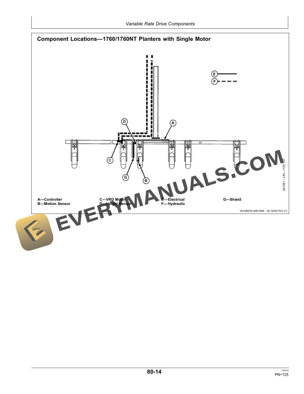
- 1.15.19. Component Locations1760/1760NT Planters with Single Motor
- 1.15.20. Component Locations1770 12RN Planters with Single Motor
- 1.15.21. Component Locations1760/1760NT Planters with Dual Motors
- 1.15.22. Component Locations1770 12RN Planters with Dual Motors
- 1.15.23. Component Locations1770 12 Row Wide
- 1.15.24. Component Locations1770NT 12 Row and 16 Row
- 1.15.25. Component Locations1770NT 24 Row
- 1.15.26. Component Locations1790 24R20
- 1.15.27. Component Locations1790 23/24 Row 15
- 1.15.28. Component Locations1790 31/32 Row 15
- 1.15.29. Component LocationsDeere/Bauer with Dual Motors
- 1.15.30. Component LocationsDeere/Bauer with Three Motors
- 1.15.31. Component LocationsDeere/Bauer with Four Motors
- 1.16. Attach and Detach Variable Rate Drive
- 1.16.1. Use Your Tractor and Machine Operators Manuals
- 1.16.2. Making Proper Hose Connections
- 1.16.3. Series Tractors Without Power BeyondSingle Motor
- 1.16.4. Series Tractors Without Power BeyondDual Motor
- 1.16.5. Series Tractors With Power Beyond Load SenseSingle Motor
- 1.16.6. Series Tractors With Power Beyond Load SenseDual Motor
- 1.16.7. , 8000, 9000 Series Tractors Without Power BeyondSingle Mot
- 1.16.8. , 8000, 9000 Series Tractors Without Power BeyondMultiple M
- 1.16.9. Series Tractors With Power Beyond Load SenseSingle Motor
- 1.16.10. Series Tractors With Power Beyond Load SenseDual Motor
- 1.16.11. Series Tractors With Power Beyond Load SenseSingle Motor
- 1.16.12. Series Tractors With Power Beyond Load SenseMultiple Motor
- 1.16.13. Series Tractors With Power Beyond Load SenseSingle Motor
- 1.16.14. Series Tractors With Power Beyond Load SenseMultiple Motor
- 1.17. Diagnostics
- 1.17.1. Controller Hardware, Software, and Part Number Identification
- 1.17.2. Display Hardware, Software, and Part Number Identification
- 1.17.3. Sensor Status
- 1.17.4. System Voltages
- 1.17.5. Variable Rate Drive Component Activity
- 1.17.6. EPM Status
- 1.17.7. Seed Tube Sensor Test
- 1.17.8. Seed Drop Test
- 1.17.9. Timed Seed Drop Test
- 1.17.10. VRD Event Logs
- 1.17.11. VRD Motor/Valve Flush
- 1.17.12. Diagnostics Code
- 1.17.13. Rotate Seed Meters
- 1.17.14. Row Clutches
- 1.17.15. Row Clutches Self Test
- 1.17.16. Vacuum Sensor
- 1.17.17. Liquid Fertilizer Sensor
- 1.17.18. Error and Fault Codes
- 1.18. Troubleshoot
- 1.18.1. Troubleshoot GreenStar Display
- 1.18.2. Troubleshoot SeedStar
- 1.18.3. Troubleshoot RowCommand
- 1.18.4. Troubleshoot Variable Rate Drive
- 1.18.5. Troubleshoot Variable Rate Fertilizer
- 1.19. Storage
- 1.19.1. Beginning of the Season Service
- 1.19.2. Liquid Fertilizer Sensor
- 1.19.3. Vacuum Sensor
- 1.20. Specifications
- 1.20.1. Record Serial Numbers
- 1.20.2. Record Planter Options
- 1.20.3. Keep Proof of Ownership
- 1.20.4. Keep Machines Secure
- 2. Page Number
- 2.1. Section 05
- 2.2. Section 10
- 2.3. Section 15
- 2.4. Section 20
- 2.5. Section 25
- 2.6. Section 30
- 2.7. Section 35
- 2.8. Section 40
- 2.9. Section 45
- 2.10. Section 50
- 2.11. Section 55
- 2.12. Section 60
- 2.13. Section 65
- 2.14. Section 70
- 2.15. Section 75
- 2.16. Section 80
- 2.17. Section 85
- 2.18. Section 90
- 2.19. Section 95
- 2.20. Section 100
- 2.21. Section 105