Description
-
Model List:
- FC12E Flex- Wing Rotary Cutter
- FC15E Flex- Wing Rotary Cutter
- FC15M Flex- Wing Rotary Cutter
- FC20M Flex- Wing Rotary Cutter
- FC10R Flex- Wing Rotary Cutter
- FC15R Flex- Wing Rotary Cutter
- FC20R Flex-Wing Rotary Cutter
- 1. Introduction
- 1.1. Foreword
- 1.2. Product Identification
- 1.3. Trademarks
- 1.4. Glossary of Terms
- 1.5. Preliminary Checks
- 1.6. Regions and Country Versions
- 1.7. Machine Overview
- 1.8. Record FlexWing Rotary Cutter Serial Number
- 1.9. Keep Proof of Ownership
- 1.10. Keep Machines Secure
- 1.11. Recognize Safety Information
- 1.12. Understand Signal Words
- 1.13. Follow Safety Instructions
- 1.14. Use Safety Lights and Devices
- 1.15. Protect Bystanders
- 1.16. Stay Clear of Rotating Blades
- 1.17. Front and Rear Safety Shields
- 1.18. Raise Wings Safely
- 1.19. Operate Tractor and Rotary Cutter Safely
- 1.20. Operate Wings Safely When Cutting
- 1.21. Keep Riders Off Machine
- 1.22. Park Machine Safely
- 1.23. Leaving Rotary Cutter Unattended
- 1.24. Prepare for Emergencies
- 1.25. Wear Protective Clothing
- 1.26. Stay Clear of Rotating Drivelines
- 1.27. Tow Loads Safely
- 1.28. Observe Maximum Transport Speed
- 1.29. Tire Maximum Transport Speeds
- 1.30. Transport Safely
- 1.31. Use a Safety Chain
- 1.32. Avoid Serious Injury or Death from Accidental Lowering of Rotary Cutter
- 1.33. Practice Safe Maintenance
- 1.34. Avoid HighPressure Fluids
- 1.35. Deliver Safely
- 1.36. Safety Features
- 2. Safety Signs
- 2.1. Replace Safety Signs
- 2.2. Safety SignsDrivelines
- 2.3. Safety SignsDriveline Shields
- 2.4. Safety SignsAxle
- 2.5. Safety SignsDeck
- 2.6. Safety SignsParking Stand
- 2.7. Safety SignsJackstand
- 3. Preparing the Tractor
- 3.1. Choosing Correct PTO Speed
- 3.2. Matching PTO Driveline and PTO Shaft
- 3.3. Recommended Tractor
- 3.4. Position Tractor Drawbar
- 3.5. Removing Quick Coupler Hitch (If Equipped)
- 3.6. Adjusting Hydraulic Flow Rate
- 3.7. Setting Tractor Wheel Tread Width
- 4. Preparing the Machine
- 4.1. Prestarting Checklist
- 4.2. Connecting Driveline Shield Chains
- 4.3. Rotary Cutter Wheel Spacing
- 4.3.1. NonRow Crop Application
- 4.3.2. Row Crop Application
- 4.4. Wheel Spacing Diagram for Row CropsFC12E
- 4.5. Wheel Spacing per Suspension
- 4.6. Wheel Spacing Diagram for Row CropsFC15M and FC15R
- 4.7. Wheel Spacing Diagram for Row CropsFC20M and FC20R
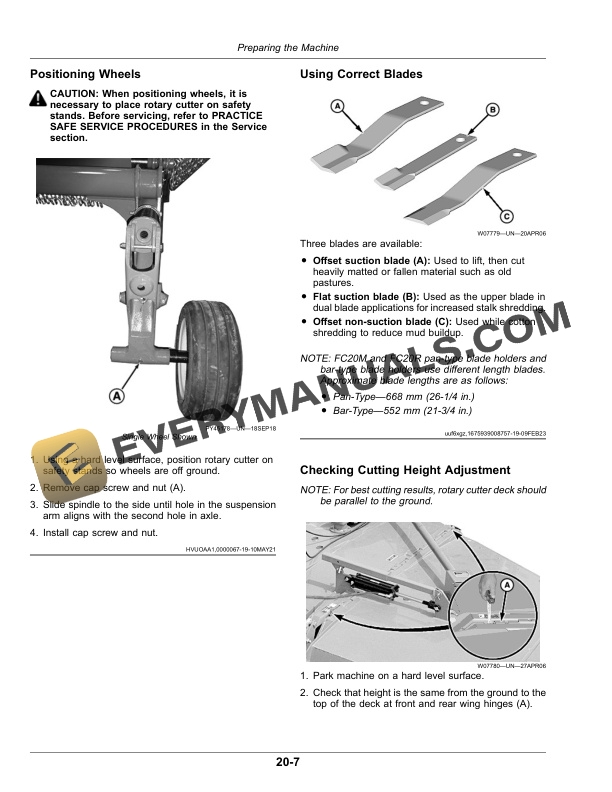
- 4.8. Positioning Wheels
- 4.9. Using Correct Blades
- 4.10. Checking Cutting Height Adjustment
- 4.11. Leveling the Rotary Cutter (All Models)
- 4.12. Checking Lighting Equipment
- 5. Attaching and Detaching
- 5.1. Attach Rotary Cutter to Tractor Drawbar
- 5.2. Assemble Main PTO Driveline Telescoping Members
- 5.3. Attach PTO Driveline
- 5.4. Attaching to Tractor Hydraulic System
- 5.5. Detach Rotary Cutter From Tractor
- 5.6. Connecting Tail/Warning Light Wiring Harness to Tractor
- 6. Transporting
- 6.1. Prepare Rotary Cutter for Transport
- 6.2. Follow Safe Transport Procedures
- 6.3. Driving Rotary Cutter In Turns
- 6.4. Keep Riders Off Machine
- 7. Operating the Machine
- 7.1. Prepare Rotary Cutter for Operation
- 7.2. Adjust Cutting Height
- 7.3. Lowering Wings
- 7.4. Follow Safe Operating Procedures
- 7.5. Operating Rotary Cutter
- 7.6. Using Safety Shields
- 7.7. Using Correct PTO Speed
- 7.8. Cutting Applications
- 7.9. Wing Flotation
- 7.10. Making Turns
- 7.11. Raising Wings
- 7.12. Operators Manual Storage Location
- 7.13. Attachments Available
- 8. Lubrication and Maintenance
- 8.1. Lubricating and Maintaining Machine Safely
- 8.2. Multipurpose Extreme Pressure (EP) Grease
- 8.3. Gear Case Oil
- 8.4. Alternative and Synthetic Lubricants
- 8.5. Mixing of Lubricants
- 8.6. Lubricant Storage
- 8.7. Perform Lubrication and Maintenance
- 8.8. Observe Lubrication Symbols
- 8.9. Service Intervals Chart
- 8.10. Keep Rotary Cutter Clean
- 8.11. Check Gear Case Oil Level
- 8.11.1. Gear Cases with Oil SightGlass
- 8.12. Lubricate HitchtoMast Bushings
- 8.13. Lubricate Wheel Support Bushings (four Locations)
- 8.14. Lubricate Axle AssemblytoFrame Bushings
- 8.15. Lubricate Wing Turnbuckles
- 8.16. Check Tire Inflation Pressure (Severe Duty Ag Tires)
- 8.17. Every 10 Hours or Daily
- 8.17.1. Keeping Rotary Cutter Clean
- 8.17.2. Checking Gear Case Oil Level
- 8.17.3. HitchtoMast Bushings
- 8.17.4. Wheel Support Bushings (4 Locations)
- 8.17.5. Axle AssemblytoFrame Bushings
- 8.17.6. Wing Turnbuckles
- 8.17.7. Input Drivelines
- 8.17.8. Gear Case Drivelines
- 8.17.9. Checking Tire Inflation Pressure (Severe Duty Ag Tires)
- 8.17.10. Air SpringsFC10R, FC15R and FC20R
- 8.18. Check Rubber Suspension Element
- 8.19. Check Wear Shoes Hardware
- 8.20. Lubricate Swivel Hitch If equipped (FC15R, FC15M and FC10R)
- 8.21. Lubricate Input Drivelines
- 8.22. Lubricate Gear Case Drivelines
- 8.23. Tighten Blade Holder Hardware
- 8.24. Tighten Blade Hardware
- 8.25. Tighten Gear Case Hardware
- 8.26. Tighten Wheel and Wheel Support Hardware
- 8.27. Driveline Inner Shaft
- 8.28. Wing Hinges
- 8.29. Grease Wheel Bearings
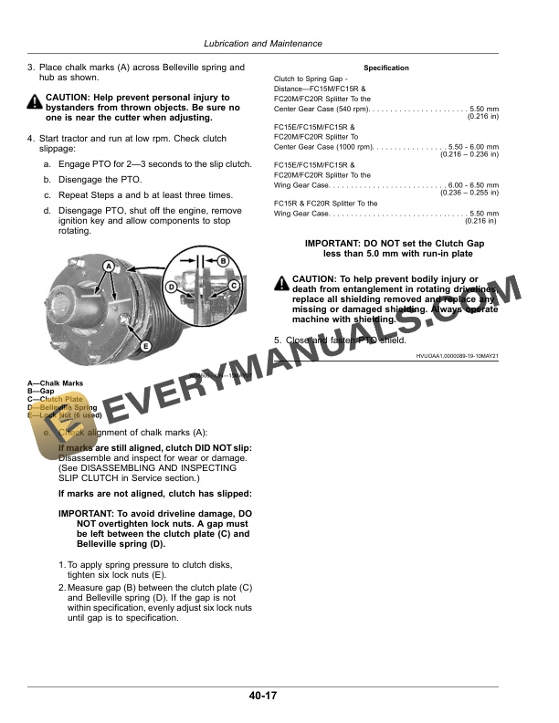
- 8.30. Change Gear Case Oil
- 8.31. As Required
- 8.31.1. Checking Driveline Shields
- 8.31.2. Freeing Slip Clutch
- 9. Service
- 9.1. Practice Safe Service Procedures
- 9.2. Work in Clean Area
- 9.3. Service Tires Safely
- 9.4. Service Severe Duty Ag Tires Safely
- 9.5. Disassembling and Inspecting Slip Clutch (FC15M, FC20M, FC15R and FC20R)
- 9.6. Assembling Slip Clutch (FC15M, FC20M, FC15R, and FC20R)
- 9.7. Assembling Slip Clutch (FC12E and FC15E)
- 9.8. Hydraulic Cylinder Requirement
- 9.9. Removing and Installing Driveline Splitter to the Center Gear Case
- 9.10. Removing and Installing PTO Driveline
- 9.11. Removing and Installing Wing Drivelines
- 9.12. Check Blade for Wear
- 9.13. Check Bolt for Wear
- 9.14. Replacing BladesRound Pan Holder
- 9.15. Replacing BladesBarType Holder
- 9.16. Installing Blades (Blade Bolt and Bushing Hardware Equipped Only)
- 9.17. Direction of Blade Rotation
- 9.18. Tighten Hardware of Torsional Suspension Axle
- 9.19. Replacing Wear Shoes
- 9.20. Replacing Axle Suspension SpringFC15M and FC20M
- 9.21. Replacing Axle Suspension Air Springs and Shock AbsorbersCX15 and CX20 a FC10R, FC15R and FC20R
- 9.22. Troubleshooting Chart
- 9.23. Metric Bolt and Screw Torque Values
- 9.24. Unified Inch Bolt and Screw Torque Values
- 10. Assembly
- 10.1. Perform Predelivery Service Safely
- 10.2. Install Optional Equipment or Attachments
- 10.3. Adjust Hydraulic Hose Lengths
- 10.4. Remove Shipping Dunnage and Parts
- 10.5. Connect Driveline Shield Chains
- 10.6. Fill Gear Case
- 10.6.1. Gear Cases with Oil SightGlass
- 10.7. Final Inspection and Adjustments
- 11. Specifications
- 11.1. FC12E Specifications
- 11.2. FC15E Specifications
- 11.3. FC15M Specifications
- 11.4. FC20M Specifications
- 11.5. FC15R and FC10R Specifications
- 11.6. FC20R Specifications
- 12. John Deere Service Literature
- 12.1. Technical Information
- 13. John Deere Service Keeps You On The Job
- 13.1. John Deere Is At Your Service