
Description
Table of contents
FOREWORD
Section 10 – GENERAL
Group 05 – Safety
Recognize Safety Information
Understand Signal Words
Practice Safe Maintenance
Park Windrower Safely
Prepare for Emergencies
Service Machines Safely
Practice Safe Service Procedures
Use Adequate Service Facilities
Support Machine Properly
Use Proper Tools
Wear Protective Clothing
Work in Clean Area
Avoid Harmful Asbestos Dust
Work In Ventilated Area
Illuminate Work Area Safely
Use Proper Lifting Equipment
Stay Clear of Rotating Driveline
Construct Dealer-Made Tools Safely
Remove Paint Before Welding or Heating
Handle Fluids Safely—Avoid Fires
Service Cooling System Safely
Service Accumulator Systems Safely
Service Tires Safely
Handling Batteries Safely
Prevent Battery Explosions
Prevent Acid Burns
Precautions for Welding
Servicing Electronic Control Units
Welding Near Electronic Control Units
Keep Electronic Control Unit Connectors Clean
Handle Electronic Components and Brackets Safely
Avoid High-Pressure Fluids
Wait Before Opening High-Pressure Fuel System
Avoid Heating Near Pressurized Fluid Lines
Replace Safety Signs
Dispose of Waste Properly
Live With Safety
Group 10 – General Information
W150 Self-Propelled Windrower Specifications Specifications and design subject to change without notice.
Dimensions
Metric Bolt and Screw Torque Values
Unified Inch Bolt and Screw Torque Values
Face Seal Fittings Assembly and Installation—All Pressure Applications
SAE Face Seal Fitting Torque Chart—Standard Pressure Applications
SAE Face Seal Fitting Torque Chart—High Pressure Applications
Four Bolt Flange Fittings Assembly and Installation—All Pressure Applications
SAE Four Bolt Flange Cap Screw Torque Values—High Pressure Applications
Service Recommendations For 37° Flare and 30° Cone Seat Connectors
Product Identification Number Plate
Windrower Product Identification Number Plate Location
Group 15 – Fuel, Coolant, and Lubricants
Diesel Fuel
BioDiesel Fuel
Diesel Fuel Storage
Lubricity of Diesel Fuel
Heavy Duty Diesel Engine Coolant
Diesel Engine Coolant (engine with wet sleeve cylinder liners)
Testing Diesel Engine Coolant
Additional Information About Diesel Engine Coolants and John Deere COOL-GARD™ II Coolant Extender
Drain Intervals for Diesel Engine Coolant
John Deere COOL-GARD™ II Coolant Extender
Supplemental Coolant Additives
Mixing of Lubricants
Diesel Engine Oil — Tier 3 and Stage III
Diesel Engine Break-In Oil — Non-Emissions Certified and Certified Tier 1, Tier 2, Tier 3, Stage I, Stage II, and Stage III
Hydraulic Systems Oil
Final Drive Oil
Grease
Alternative and Synthetic Lubricants
Lubricant Storage
Section 20 – ENGINE
Group 00 – Component Removal and Installation
Specifications
Other Material
Remove and Install Hood
Remove and Install Engine Fan
Remove and Install Radiator
Remove and Install Rotating Wand Screen
Remove and Install Air Conditioning Compressor Belt
Remove and Install Alternator Belt
Remove and Install Oil Cooler/Air Conditioning Condenser
Remove and Install Muffler
Remove and Install Engine Gear Case
Group 05 – Engine
Other Material
Specifications
Adjust Hood
Engine Gearcase Check and Adjustment
Hood Position
Group 10 – Cooling System
Specifications
Inspect Radiator Cap
Drain, Flush, and Fill Cooling System
Section 30 – FUEL AND AIR
Group 00 – Component Removal and Installation
Specifications
Remove and Install Fuel Tank
Remove and Install Secondary Fuel Filter
Remove and Install Primary Fuel Filter
Remove and Install Fuel Line Vent Filter
Remove and Install Charge Air Cooler
Remove and Install Air Filter Housing
Remove and Install Air Filter Elements
Remove and Install Fuel Cooler
Group 05 – Air Intake System
Inspect Air Filters
Group 10 – Diesel Fuel System
Bleed Fuel System
Drain Fuel Tank
Section 40 – ELECTRICAL
Group 05 – Battery
Remove and Install Battery
Connecting Booster Battery
Charging Battery
Checking Specific Gravity
Add Electrolyte
Group 10 – Switches, Sensors, and Modules
Specifications
Remove and Install Linkage Arm Neutral Start Switch
Remove and Install Throttle Sensor
Remove and Install Multi-Function Lever Position Switch
Remove and Install Multi-Function Lever Switch Panel
Remove and Install Air Conditioning Low Pressure Switch
Remove and Install Air Conditioning High Pressure Switch
Remove and Install Seat Base Position Switch
Remove and Install Float Sensor
Remove and Install Air Conditioning Thermostatic Control Switch
Remove and Install Hydraulic Oil Level Switch
Remove and Install Hydraulic Oil Temperature Switch
Remove and Install Header Height Sensor
Remove and Install Header Angle Sensor
Remove and Install Traction Supercharge Pressure Switch
Remove and Install Header Supercharge Switch
Remove and Install Brake Pressure Switch
Remove and Install Filter Pressure Differential Switch
Remove and Install Seat Switch
Remove and Install Engine Temperature and Fuel Gauges
Remove and Install Cab Display Module
Remove and Install Windrower Control Module
Group 15 – Engine Electrical Components
Specifications
Remove and Install Rotating Wand Drive
Group 20 – Fuses and Relays
Fuses and Relays
Group 25 – Harness and Connector Repair
Other Material
Use Electrical Insulating Compound
Using High-Pressure Washers
Electrical System Visual Inspection
Basic Electrical Component Handling / Precautions for Vehicles Equipped with Computer Controlled Systems
Electrical Connector / Wiring Harness Handling and Repair
Repair Procedure R-A
Repair Procedure R-B
Repair Procedure R-C
Repair Procedure R-D
Repair Procedure R-E
Repair Procedure R-F
Repair Procedure R-G
Repair Procedure R-I
Repair Procedure R-J
Repair Procedure R-K
Repair Procedure R-M
Repair Procedure R-N
Repair Procedure R-AE
Repair Procedure R-AF
Repair Procedure R-AG
Repair Procedure R-AH
Repair Procedure R-AI
Repair Procedure R-AJ
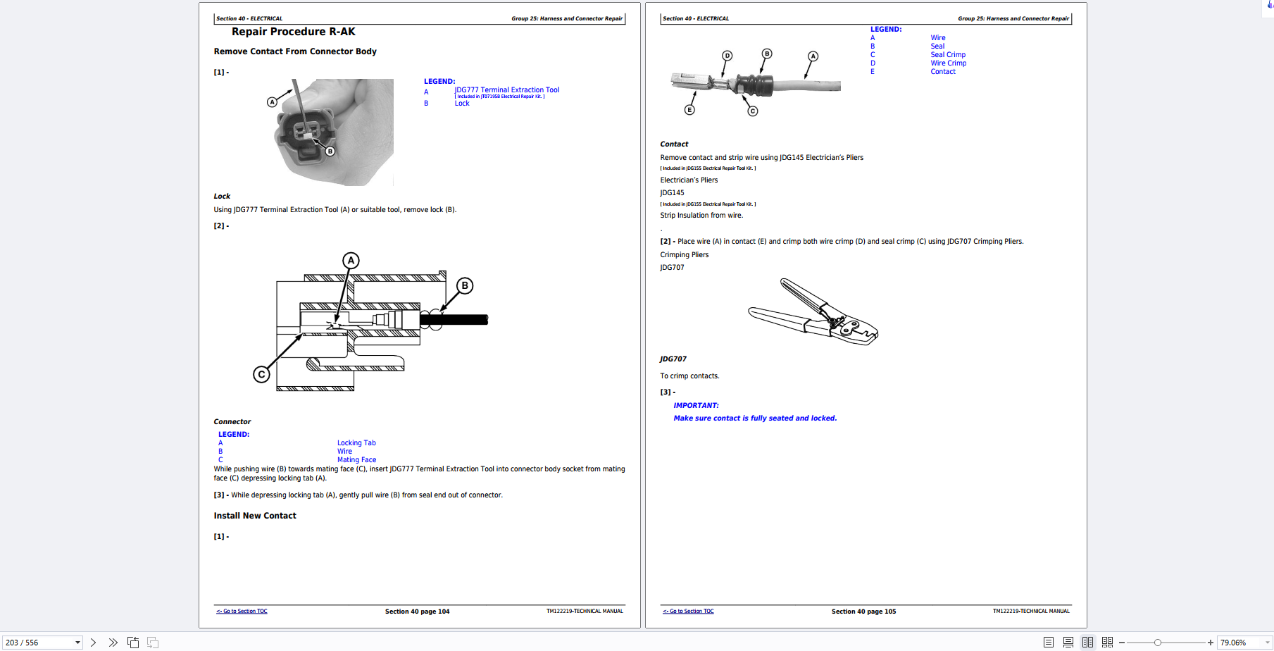
Repair Procedure R-AK
Repair Procedure R-AL
Group 30 – Starter
Remove and Install Starter
Group 35 – Alternator
Remove and Install Alternator
Section 50 – POWER TRAIN
Group 00 – Component Removal and Installation
Other Material
Specifications
Drive Pump Port Identification and Pressure
Remove and Install Traction Drive Pump
Remove and Install Planetary Final Drive and Drive Wheel Motor
Remove and Install Drive Wheel
Group 05 – Traction Drive
Special Tools
Other Material
Traction Drive Pump Rebuild Startup Procedure
Traction Drive Pump Exploded View
Disassemble and Assemble Final Drive With Internal Brake
Disassemble and Assemble Internal Park Brake
Section 60 – STEERING
Group 00 – Component Removal and Installation
Specifications
Remove and Install Steering Servo Assembly
Group 05 – Steering
Other Material
Specifications
Disassemble and Assemble Steering Servo Assembly
Section 70 – HYDRAULIC SYSTEM
Group 00 – Component Removal and Installation
Specifications
Remove and Install Auxiliary Pads
Remove and Install Header Drive Pump
Remove and Install Hydraulic Reservoir
Group 05 – Hydraulic Pumps
Other Material
Specifications
Bleed Header Drive Pump
Remove and Install Charge Pump and Auxiliary Pump Mounting Pad (Variable Pump)
Filtration and Charge Pump Options
Remove and Install Integral Charge Pump (Tandem Pump)
Knife Drive Pump Exploded View
Remove and Install Knife Drive Pump Seal
Remove and Install Rear Shaft Cover (Tandem Pump)
Remove and Install Rear Shaft Cover (Tandem Pump) Auxiliary Pump Mounting Pad
Reel and Conveyor Pump Exploded View
Remove and Install Tandem Pump Shaft Seals
Remove and Install Tandem Pump Trunnion Cover (Plain)
Remove and Install Tandem Pump Trunnion Seal (Control Shaft Side)
Group 10 – Hydraulic Valves
Specifications
Disassemble and Assemble Knife Drive Control Valve
Remove and Install Charge Pressure Relief Valve
Remove and Install Check and High Pressure Relief Valves
Section 90 – OPERATOR STATION
Group 00 – Component Removal and Installation
Other Material
Specifications
Remove and Install Front Windshield Wiper Motor
Remove and Install Rear Windshield Wiper Motor
Remove and Install Front Cab Windshield
Remove and Install Steering Column
Remove and Install Cab Door
Remove and Install Seat
Remove and Install Seat Base
Remove and Install Evaporator Core
Remove and Install Door Handle
Remove and Install Cab Roof
Group 05 – Cab
Adjust Door
Centering Steering Wheel
Group 10 – Air Conditioning
Special Tools
Replace Thermostat Capillary Tube
Compressor Oil Level Check
Air Conditioning Refrigerant Oil
Charge Air Conditioning System
Discharge Air Conditioning System
Evacuate Air Conditioning System
Purge Air Conditioning System
Section 211 – DIAGNOSTIC TROUBLE CODES
Group 10 – CDM – Diagnostic Trouble Codes
Cab Display Module – Diagnostic Trouble Codes
Group 15 – ECU – Diagnostic Trouble Codes
ECU – Diagnostic Trouble Codes
Section 220 – ENGINE AND ENGINE EXHAUST
Group 20 – Theory of Operation
Radiator Screen Theory of Operation
Section 230 – FUEL AND AIR INTAKE
Group 20 – Theory of Operation
Air Intake System Theory of Operation
Fuel System Priming Theory of Operation
Section 240 – ELECTRICAL
Group 05 – General Information
Electrical Troubleshooting
Wire Identification Convention
Group 10 – CanWin
CanWin General Information
CanWin Chassis I/O Page
CanWin Display I/O Page
CanWin Header I/O Page
CanWin Frequency/Analog Page
CanWin Program CANBUS Page
Group 20 – Theory of Operation
Throttle Lever Theory of Operation
Starting Circuit Theory of Operation
Header Recognition Circuit Theory of Operation
Header Height Sensor Circuit Theory of Operation
Header Tilt Theory of Operation
Group 30 – Schematic
Electrical Schematic
Group 50 – Diagnostic Tests and Adjustments
Specifications
Starting Circuit Operational Check
Testing Relays
Windrower Control Module/Cab Display Module Power Failure or System Failure (Header Down)
Speed Sensor Adjustment
Relief Valve Check and Adjustment
Header Recognition Circuit Diagnostic
Header Height Sensor Circuit Diagnostic
Section 249 – ELECTRICAL COMPONENT INFORMATION
Group 05 – General Information
How to use the Connector Information (end views, numbers, location photos)
Group 40A – Electrical Assemblies
Windrower Control Module Connector (P34)
Windrower Control Module Connector (P35)
Windrower Control Module Connector (P36)
Radio Connector (P15)
Group 40B – Sensors
Left-Hand Wheel Speed Connector (P81)
Header Height Connector (P82)
Header Angle Connector (P83)
Right-Hand Float Connector (P84)
Left-Hand Float Connector (P85)
Reel Speed Connector (P87)
Knife-Disk Speed Connector (P88)
Group 40E – Lights
Left-Hand Work Light (High-Low Beam) Connector (P26B)
Right-Hand Work Light (High-Low Beam) Connector (P26C)
High-Low Beam Relay Connector (P104)
Field Lights, Road Lights Relay Connector (P105)
Right-Hand (Cab Forward) Turn Light, Tail Light Connector (P107)
Left-Hand (Cab Forward) Turn Light, Tail Light Connector (P111)
Left-Hand Side Work Light Connector (P117)
Left-Hand Corner Work Light Connector (P118)
Left-Hand Inside Work Light, High Beam Connector (P119)
Center Lamp Connector (P120)
Right-Hand Inside Work Light, High Beam Connector (P121)
Right-Hand Corner Work Light Connector (P122)
Right-Hand Side Work Light Connector (P123)
Left-Hand Rear Side Lamp Connector (P124)
Right-Hand Tail/Stop Lamp Rear Connector
Left-Hand Tail/Stop Lamp Rear Connector
Beacon Relay Connector
Group 40P – Gauges
Engine Temperature Gauge Connector (P42)
Fuel Level Gauge Connector (P47)
Group 40K – Relays
K17 Starter Relay (P9)
Group 40M – Motors
Screen Sweepers Connector (P107)
Group 40S – Switches
Blower Speed Connector (P23)
Neutral Switch Linkage Arm Connector (P24)
Seat Position (Cab End) Connector (P32)
Seat Position (Engine End) Connector (P33)
Ignition Switch Connector (P8)
Air Conditioning On-Off Connector (P19)
Recirculation Fan Connector (P28)
Rear Auxiliary Power 1 Switch (PWR 1)
Rear Auxiliary Power 2 Switch (PWR 2)
Group 40X – Interconnects and Ground Points
Header Connector (C1A)
Roof Connector (C2A)
Roof Connector (C3A)
Roof Connector (C3B)
Cab Connector (C4A)
Left-Hand Wheel End Connector (C6A)
Right-Hand Wheel End Connector (C7A)
Roof Connector (P2B)
Roof Connector (P2C)
Roof Connector (P2D)
Front Wiper Connector (P11)
Rear Wiper (Engine End) Connector (P12)
Cab End Wiper Connector (P13)
Radio Memory Connector (P16)
Air Conditioning Compressor Clutch Connector (P18)
Air Conditioning System Connector (P22)
Hood Connector (P26A)
Temperature Control Connector (P27)
Fresh Air Boost Connector (P29)
CAN Stub Connector (P40)
Antenna Ground
Ground Point A Frame Rail
Ground Point B Engine Block
Ground Point D
Ground Point E
Ground Point F
Cab Display Module Ground
Group 40Y – Electronically Actuated Mechanical Devices
Brake Connector (P44)
Load Sense Dump Connector (P75)
Pressure Transducer Connector (P97)
Section 250 – DRIVE TRAIN
Group 20 – Theory of Operation
Linkage Arm Neutral Switch Theory of Operation
Neutral Interlock and Steering Theory of Operation
Interlock Pivot Channel Theory of Operation
Wheel Motor Speed Theory of Operation
Neutral Adjustment Theory of Operation
Traction Pump Interlock Theory of Operation
Hydraulic Lift Block Theory of Operation
Group 50 – Diagnostic Tests and Adjustments
Specifications
Steering and Neutral Switch Troubleshooting
Interlock Pivot Channel Clearance Check and Adjustment
Neutral Switch Linkage Arm Check and Adjustment
Traction Pump Interlock Check and Adjustment
Equalize Neutral Inside Cab Check and Adjustment
Servo Input Check and Adjustment
Neutral Adjustment Chart
Neutral Fine Check and Adjustment
Neutral Adjustment Checks
Wheel Motor Adjustment—High Speed
Wheel Motor Adjustment—Low Speed
Wheel Motor Adjustment—Mid Range
Section 260 – STEERING AND BRAKES
Group 20 – Theory of Operation
Brake Circuit Theory of Operation
Group 50 – Diagnostic Tests and Adjustments
Brake Circuit Operational Check
Park Brake Circuit Operational Check
Park Brake Circuit Pressure Check
Section 270 – HYDRAULICS
Group 20 – Theory of Operation
Center Link Self Alignment Theory of Operation
Charge Pump (Furthest from Engine) Theory of Operation
Cooler Bypass Test Theory of Operation
Double Windrow Attachment Theory of Operation
Header Drive Theory of Operation
Header Return Manifold Theory of Operation
Hydraulic Filter Theory of Operation
Hydraulic Fore-Aft Theory of Operation
Multi-Function Control Block Theory of Operation
Piston Pumps Theory of Operation
Secondary (Fine) Float Adjustment Circuit Theory of Operation
Super Charge Pressure Valve Block Theory of Operation
Reel and Conveyer Test with Draper Head Theory of Operation
Reel and Auger Test with Auger Head Theory of Operation
Group 30 – Schematic
Hydraulic Schematics
Group 50 – Diagnostic Tests and Adjustments
Specifications
Combination Valve Relief Setting Check and Adjustment
Cooler Bypass System Check and Adjustment
Header Charge Pressure System Checks
Header Hydraulic Check and Adjustment
Hydraulic Filter System Check and Adjustment
Super Charge Pressure Valve Block Check and Adjustment
Reel and Conveyor Test with Draper Header Checks
Reel and Auger Test with Auger Header Check and Adjustment
Knife Drive Check and Adjustment
Secondary (Fine) Float Adjustment Circuit
Section 290A – HEATING, VENTILATION, AND AIR CONDITIONING
Group 20 – Theory of Operation
Air Conditioning Circuit Theory of Operation
Heating and Air Conditioning Theory of Operation
Heating and Air Conditioning Components Theory of Operation
Group 50 – Diagnostic Tests and Adjustments
Air Conditioning Performance Troubleshooting
Heater Valve Diagnostics
Section 299 – DEALER FABRICATED TOOLS
Group 05 – Dealer Fabricated Tools
DFEXT5 Steering Wheel Removal Tool