Description
-
Model List:
- 225 Disk Harrow Wheel Type Offset
- 1. Contents
- 1.0.1. Recognize Safety Information
- 1.0.2. Understand Signal Words
- 1.0.3. Follow Safety Instructions
- 1.0.4. Use Seat Belt Properly
- 1.0.5. Park Machine Safely
- 1.0.6. Keep Riders Off Machine
- 1.0.7. Prepare for Emergencies
- 1.0.8. Use Safety Lights and Devices
- 1.0.9. Wear Protective Clothing
- 1.0.10. Use a Safety Chain
- 1.0.11. Tow Loads Safely
- 1.0.12. Observe Maximum Transport Speed
- 1.0.13. Practice Safe Maintenance
- 1.0.14. Remove Paint Before Welding or Heating
- 1.0.15. Avoid HighPressure Fluids
- 1.0.16. Store Attachments Safely
- 1.1. Preparing the Tractor
- 1.1.1. Tractor Size
- 1.1.2. Tire Pressure
- 1.1.3. Rear Wheel Weighting (1) Front end Weighting (2)
- 1.1.4. Wheel Tread
- 1.1.5. Rockshaft control lever
- 1.1.6. Drawbar
- 1.1.7. Pin drawbar
- 1.1.8. Hydraulics
- 1.1.9. Hydraulic Cylinder
- 1.2. Preparing the Machine
- 1.2.1. Hardware
- 1.2.2. Lubrication
- 1.2.3. Tire Inflation
- 1.2.4. Initial Settings
- 1.3. Attaching and Detaching
- 1.3.1. Positioning drawbar
- 1.3.2. Straight or offset drawbar
- 1.3.3. Safety Chain
- 1.3.4. Remote Cylinder Control Lever
- 1.3.5. Use Correct Hose Tips
- 1.3.6. Attaching disk to tractor
- 1.3.7. Attaching the hitch to drawbar
- 1.3.8. Detaching from tractor
- 1.3.9. Remote cylinder operating speed
- 1.3.10. Quick Coupler
- 1.4. Transporting
- 1.4.1. Use a Safety Chain
- 1.4.2. Use Safety Lights and Devices
- 1.4.3. Tow Loads Safely
- 1.4.4. Observe Maximum Transport Speed
- 1.4.5. Disk Width
- 1.4.6. Transport Safely
- 1.4.7. Leveling Disk for Transport
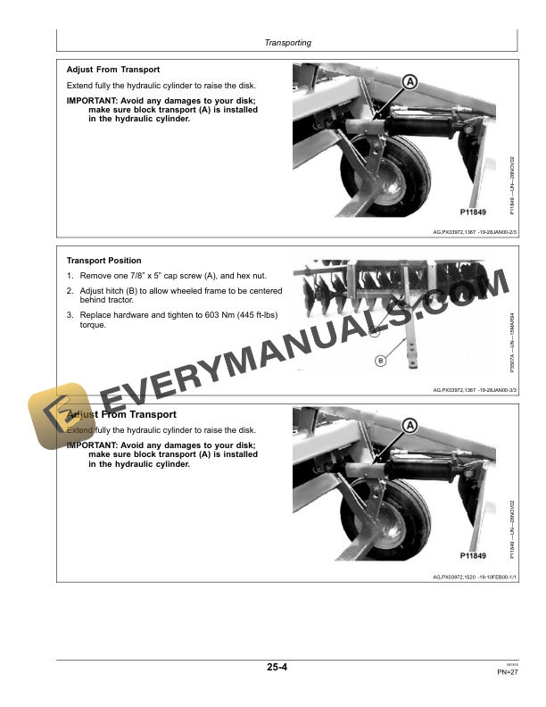
- 1.4.8. Adjust From Transport
- 1.4.9. Drawbar
- 1.4.10. Remote Cylinder
- 1.4.11. Tire Inflation
- 1.4.12. Angling Hitch for Transport
- 1.5. Operating the Machine
- 1.5.1. Before Operating the Disk
- 1.5.2. Removing the Disk from Transport
- 1.5.3. Sequence of Field Adjustments
- 1.5.4. Leveling the Disk
- 1.5.5. Adjusting the Hitch
- 1.5.6. Correcting Side Draft
- 1.5.7. Adjusting Disking Depth
- 1.5.8. Filling Furrows
- 1.5.9. Lateral gang Adjustment
- 1.6. Attachments
- 1.6.1. Furrow Filler
- 1.6.2. Furrow Filler Disk Scraper
- 1.6.3. Bearing wear guard
- 1.6.4. Disk Blades
- 1.6.5. Wheels and Tires
- 1.6.6. Attachments for Field Conversion
- 1.7. Lubrication and Maintenance
- 1.7.1. Alternative and Synthetic Lubricants
- 1.7.2. Lubricant Storage
- 1.7.3. Lubrication Symbols
- 1.7.4. Bearing and end of Season
- 1.7.5. Lubricate Gang Bearings
- 1.7.6. Transport Wheels and Mechanism
- 1.7.7. Lubrication Symbols
- 1.7.8. Bearing and end of Season
- 1.7.9. Lubricate Gang Bearings
- 1.7.10. Lubricate Wheel Bearings
- 1.8. Troubleshooting
- 1.8.1. Troubleshooting
- 1.9. Service
- 1.9.1. General
- 1.9.2. Disk Gangs
- 1.9.3. Storage
- 1.9.4. Disassembling disk gangs
- 1.9.5. Tire Inflation Pressure Chart
- 1.9.6. Identifying Disk Blades Eligible for Warranty
- 1.9.7. Identifying Disk Blades not Eligible for Warranty
- 1.10. Storage
- 1.10.1. Store Attachments Safely
- 1.10.2. Storage
- 1.11. Assembly
- 1.11.1. Assembly
- 1.11.2. Main Frame
- 1.11.3. Attaching Axle
- 1.11.4. Attaching Wheels and Lift Bar
- 1.11.5. Assembling Gangs
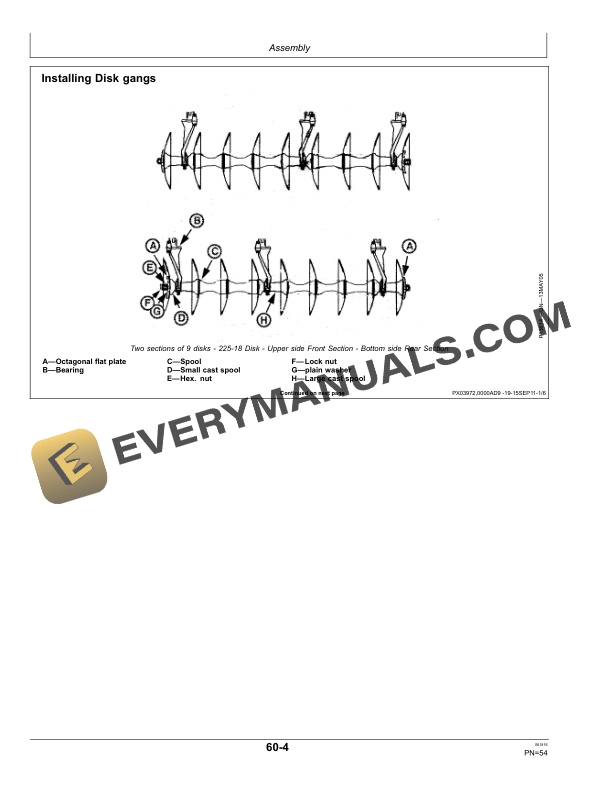
- 1.11.6. Installing Disk gangs
- 1.11.7. Attaching Gang Frames to Main Frame
- 1.11.8. Replacing Scrapers
- 1.11.9. Assembling sleeve and bearings
- 1.11.10. Tighten gang bolts
- 1.11.11. Attaching disk gang to standards
- 1.11.12. Standard Ubolt tightening sequence
- 1.11.13. Tightening scraper angle bolt nuts
- 1.11.14. Assemble gangs
- 1.11.15. Install standards to gang frame
- 1.11.16. Attach gang frames to main frame
- 1.11.17. Bearings wear guard
- 1.11.18. Safety reflectors
- 1.11.19. SMV Installation
- 1.11.20. Warning lights
- 1.11.21. Route wiring harness
- 1.11.22. Tail lamp
- 1.12. Specifications
- 1.12.1. Unified Inch Bolt and Screw Torque Values
- 1.12.2. Metric Bolt and Screw Torque Values
- 1.12.3. Specifications
- 1.12.4. Specifications
- 1.12.5. Tapered Gangs
- 1.12.6. Furrow Filler
- 1.12.7. Recommended PTO Horsepower
- 1.12.8. Product Identification Number
- 1.13. John Deere Service Literature Available
- 1.13.1. Technical Information
- 1.13.2. John Deere Parts
- 1.13.3. The Right Tools
- 1.13.4. WellTrained Technicians
- 1.13.5. Prompt Service
- 2. Page Number
- 2.1. Section 05
- 2.2. Section 10
- 2.3. Section 15
- 2.4. Section 20
- 2.5. Section 25
- 2.6. Section 30
- 2.7. Section 35
- 2.8. Section 40
- 2.9. Section 45
- 2.10. Section 50
- 2.11. Section 55
- 2.12. Section 60
- 2.13. Section 65