Description
-
Model List:
- 2430 Chisel Plow
- 1. Introduction
- 1.1. Foreword
- 1.2. A Message to Our Customers
- 1.3. Recognize Safety Information
- 1.4. Understand Signal Words
- 1.5. Follow Safety Instructions
- 1.6. Spanish Safety Signs and Operators Manual
- 1.7. Prepare for Emergencies
- 1.8. Wear Protective Clothing
- 1.9. Practice Safe Maintenance
- 1.10. Handle Electronic Components and Brackets Safely
- 1.11. Support Raised Equipment
- 1.12. Remove Paint Before Welding or Heating
- 1.13. Avoid Heating Near Pressurized Fluid Lines
- 1.14. Avoid HighPressure Fluids
- 1.15. Check Hydraulic Hoses
- 1.16. Inspect Lift Circuit Hoses
- 1.17. Store Attachments Safely
- 1.18. Service Tires Safely
- 1.19. Decommissioning Proper Recycling and Disposal of Fluids and Components
- 1.20. Handle Chemical Products Safely
- 1.21. Operate Safely
- 1.22. Use Safety Lights and Devices
- 1.23. Keep Riders Off Machine
- 1.24. Observe Maximum Transport Speed
- 1.25. Use a Signal Person
- 1.26. Use a Safety Chain
- 1.27. Tow Loads Safely
- 1.28. Avoid Overhead Power Lines
- 1.29. Prepare for Transport
- 1.30. Transport Safely
- 1.31. Implements in Train Transport
- 1.32. Transport Lockup Valve
- 1.33. Do Not Fold Wings Until Machine Is Fully Raised
- 1.34. Park Safely
- 2. Safety Signs
- 2.1. Replace Damaged or Missing Safety Signs
- 2.2. Main Frame
- 2.3. Section Inner Wing
- 2.4. Wing Plates
- 2.5. Transport Locks
- 2.6. Low Transport
- 2.7. Rear HitchIf Equipped
- 2.8. Rigid Fold
- 2.9. Informational Decals
- 3. Safety Features
- 3.1. Safety Features
- 4. Preparing Tractor
- 4.1. Use Tractor Operators Manual
- 4.2. Determine Tractor Requirements
- 4.3. Drawbar Requirements
- 4.4. Secure ThreePoint Hitch
- 4.5. Power TakeOff
- 4.6. Position Drawbar
- 4.7. Prepare Hydraulic SystemJohn Deere R/RT Series Tractors
- 4.8. Use a Safety Chain
- 5. Preparing Machine
- 5.1. Drawbar Requirements
- 5.2. Check and Lubricate Machine
- 5.3. Check Tire PressureAll Tillage Machines
- 5.4. Check Wheel HardwareAll Tillage Machines
- 5.5. Tighten Hardware
- 5.6. Check and Adjust Frame Fore/Aft Level
- 5.7. Checking and Adjusting SidetoSide Level for Single Point Depth Control Machines
- 6. Attaching And Detaching
- 6.1. Use Your Tractor and Tillage Equipment Operators Manuals
- 6.2. Before Attaching Machine to Tractor
- 6.3. Attach Machine to Tractor
- 6.4. Make Proper Hose Connections
- 6.5. Attach Electrical Connectors
- 6.6. Position Jack for Transport
- 6.7. Attach Safety Chain to Tractor
- 6.8. Engage Transport Lockup Valve
- 6.9. Checking WingFold Operation
- 6.10. Checking Single Point Depth Control
- 6.11. Detach Machine From Tractor
- 7. Transporting
- 7.1. Use Safety Lights and Devices
- 7.2. Observe Maximum Transport Speed
- 7.3. Use a Safety Chain
- 7.4. Attach Safety Chain to Tractor
- 7.5. Tow Loads Safely
- 7.6. Avoid Overhead Power Lines
- 7.7. Prepare for Transport
- 7.8. Use Cylinder Locks
- 7.9. Close Transport Lockup Valve
- 7.10. Keep Riders Off Machine
- 7.11. Position Drawbar
- 7.12. Position Jack for Transport
- 7.13. Transport Machine
- 8. Operating Machine
- 8.1. Keep Riders Off Machine
- 8.2. Follow Safe Operating Procedures
- 8.3. Guidelines for Use
- 8.4. Tighten Hardware
- 8.5. Use Operators Manual Holder
- 8.6. Using Adjustment Wrench
- 8.7. Prepare to Operate Machine in Field
- 8.8. Adjust Single Point Depth Control
- 8.9. Operate TruSet Depth Control for John Deere R/RT Series Tractors
- 8.10. Bypass TruSet
- 8.11. Harrow Adjustments
- 8.12. Adjusting Harrow Tines
- 8.13. Adjust Rolling Baskets
- 8.14. Operate Optional Rear Hitch
- 9. Preparing and Operating TruSet
- 9.1. Before Operating TruSet
- 9.2. Disengage SinglePoint Depth Control
- 9.3. Access Set up Screen
- 9.4. Verify Tool Settings
- 9.5. Assign SCV Functions
- 9.6. Perform Machine Calibration
- 9.7. Adjust Cylinder RePhasing Settings
- 9.8. Adjust TruSet Tuning
- 9.9. Set Task Controller
- 9.10. Select SCV Flick Enable
- 9.11. Set Documentation Trigger
- 9.12. Choose Layout Manager
- 9.13. Understand Layout Functionality
- 9.14. Make Initial Setpoints
- 9.15. Store and Use Preset Values
- 9.16. Engage TruSet
- 9.17. Adjusting Machine Depth TruSet Machines
- 9.18. Adjusting Machine Depth TruSet Machines with External Valve
- 9.19. Adjust Incremental Step Size
- 9.20. Adjust Machine Upper Setpoint
- 9.21. Adjust Section LevelMachines with SideToSide Option ONLY
- 9.22. Understand SCV Functions
- 9.23. Perform Field Calibration
- 9.24. Activate Prescription Mode
- 10. Lubrication And Maintenance
- 10.1. Lubricating and Maintaining Machine Safely
- 10.2. Multipurpose Extreme Pressure (EP) Grease
- 10.3. Alternative And Synthetic Lubricants
- 10.4. Lubricant Storage
- 10.5. Beginning and End of Season
- 10.6. Lubrication Symbols
- 10.7. Lubrication Intervals
- 10.8. Lubricate Jack
- 10.9. Lubricate Wheel Bearings
- 10.10. Lubricate Caster Wheel Pivot Bearings
- 10.11. Lubricate Rear Swing Arm Pivots
- 10.12. Lubricate Fore/Aft Links
- 10.13. Repack Walking Beam Pivot Bearings
- 11. Troubleshooting
- 11.1. Troubleshooting Machine
- 11.2. Troubleshooting ChartTruSet
- 11.3. Troubleshooting Drawbar Hitch Links
- 11.4. Recommendations for Working Hard Soils
- 12. Service
- 12.1. Practice Safe Maintenance
- 12.2. Use Safe Service Procedures
- 12.3. Work in Clean Area
- 12.4. Service Machines Safely
- 12.5. Illuminate Work Area Safely
- 12.6. Support Machine Properly
- 12.7. Tighten Hardware
- 12.8. Metric Bolt and Screw Torque Values
- 12.9. Unified Inch Bolt and Screw Torque Values
- 12.10. Face Seal Fittings Assembly and InstallationAll Pressure Applications
- 12.11. Metric Face Seal and ORing Stud End Fitting Torque ChartStandard Pressures
- 12.12. SAE Face Seal and ORing Stud End Fitting Torque ChartStandard Pressures
- 12.13. Discarded Tires
- 12.14. Service Tires Safely
- 12.15. Check Tire PressureAll Tillage Machines
- 12.16. Repair Tire
- 12.17. Check Wheel HardwareAll Tillage Machines
- 12.18. Check CShank Assembly
- 12.19. Check Standard Bushings
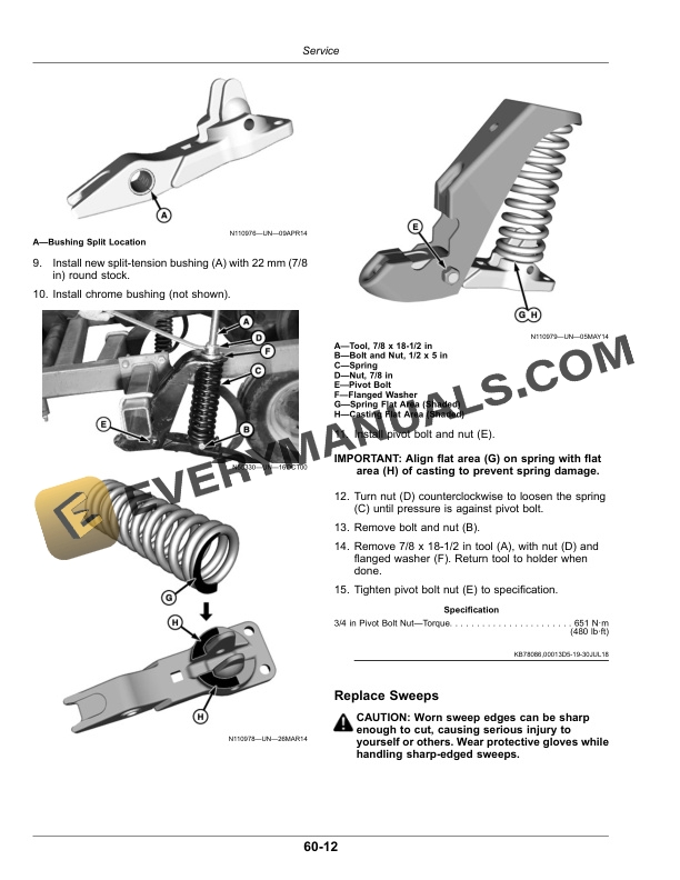
- 12.20. Replace SplitTension Bushings
- 12.21. Replace Sweeps
- 12.22. Replace Twisted Shovels
- 12.23. Checking Depth Control Hydraulic System
- 12.24. Preventing Hydraulic System Contamination
- 12.25. Checking Depth Control for Leakage
- 12.26. Analyze Test ResultsSeriesParallel System
- 12.27. Cleanliness
- 12.28. Remove Hydraulic Cylinders
- 12.29. Before Bleeding the Hydraulic System
- 12.30. Bleed Hydraulic SystemSingle Point Depth Control3.6 m (12 ft) Main Frame
- 12.31. Bleed Hydraulic SystemSingle Point Depth Control4.5 m (15 ft) Main Frame
- 12.32. Installing And Bleeding WingFold Cylinders
- 12.33. Replace Hydraulic Hoses
- 12.34. Replace Wheel Retraction Switch 3.6 m (12 ft) Main Frame ONLY
- 12.35. TruSet Components
- 12.36. TruSet Component Locations
- 12.37. AddOn Valve Components
- 13. Storage
- 13.1. Preparing For Storage
- 13.2. Removing From Storage
- 14. Specifications
- 14.1. Hitch Specifications
- 14.2. Tractor Horsepower Recommendations
- 14.3. Rigid/Rigid Fold
- 14.4. Section
- 14.5. Section
- 14.6. Hydraulic Hose Specifications
- 14.7. Download Force on Tractor Drawbar
- 14.8. Product Identification Number
- 14.9. Record Product Identification Number (PIN)
- 14.10. Record Serial NumberTruSet Machines
- 14.11. Keep Proof of Ownership
- 14.12. Keep Machines Secure
- 15. John Deere Service Literature Available
- 15.1. Technical Information
- 16. John Deere Service Keeps You On The Job
- 16.1. John Deere Is At Your Service