Description
-
Model List:
- 3710 Drawn Rigid Moldboard Plow
- 1. Contents
- 1.0.1. Recognize Safety Information
- 1.0.2. Understand Signal Words
- 1.0.3. Follow Safety Instructions
- 1.0.4. Operate Plow Safely
- 1.0.5. Keep Riders Off Machine
- 1.0.6. Wear Protective Clothing
- 1.0.7. Use Safety Lights and Devices
- 1.0.8. Use a Safety Chain
- 1.0.9. Transport Plow Safely
- 1.0.10. Observe Maximum Transport Speed
- 1.0.11. Practice Safe Maintenance
- 1.0.12. Avoid HighPressure Fluids
- 1.0.13. Check Hydraulic Hoses
- 1.0.14. Service Tires Safely
- 1.0.15. Handle Global Positioning Receivers and Brackets Safely
- 1.0.16. Remove Paint Before Welding or Heating
- 1.0.17. Avoid Heating Near Pressurized Fluid Lines
- 1.0.18. Prepare for Emergencies
- 1.1. Safety Signs
- 1.1.1. Front Furrow Wheel
- 1.1.2. Tailwheel
- 1.2. Safety Features
- 1.2.1. Safety Features
- 1.3. Preparing Tractor
- 1.3.1. Determining Tractor Requirements
- 1.3.2. Positioning Drawbar80009000 Series Tractors
- 1.3.3. Tractor Wheel SettingInFurrow Plows
- 1.3.4. Tractor Wheel SettingOnLand Plows
- 1.3.5. Front End Weighting2Wheel Drive Tractors
- 1.3.6. Drive Wheel Weighting
- 1.3.7. Adjusting Metering Valves80009000 Series Tractors
- 1.3.8. Rockshaft Height Stop Lock
- 1.4. Preparing Machine
- 1.4.1. Checking And Lubricating Machine
- 1.4.2. Checking Wheel Bolts and Bearings
- 1.4.3. Tightening Hardware
- 1.4.4. Preparing Plow Bottoms
- 1.4.5. Positioning Drawbar Tube
- 1.4.6. Setting AdjustOCut For Width Of Cut
- 1.4.7. Setting Hitch Tube
- 1.4.8. InFurrow Plow Hitch Settings
- 1.4.9. OnLand Plow Hitch Settings
- 1.4.10. Running InFurrow With OnLand Hitch
- 1.4.11. Setting Front Furrow Wheel
- 1.4.12. Setting Tailwheel Lock
- 1.5. Attaching and Detaching
- 1.5.1. Attaching Machine Safely
- 1.5.2. Making Proper Hose Connections
- 1.5.3. Attaching Machine To Tractor
- 1.5.4. Attaching Warning Light Plug
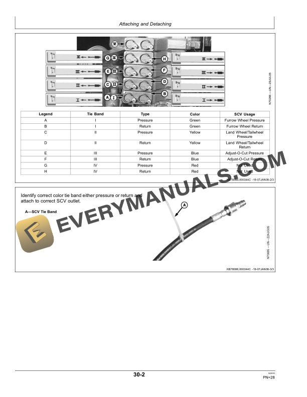
- 1.5.5. Attaching Hydraulic Hoses80009000 and 80309030 Series Tractor
- 1.5.6. Checking Hydraulic System
- 1.5.7. Detaching From Tractor
- 1.6. Transporting
- 1.6.1. Attach Safety Chain to Tractor
- 1.6.2. Using Warning Lights
- 1.6.3. Installing Transport Lock On Furrow Wheel Cylinder
- 1.6.4. Installing Transport Lock On Tailwheel Cylinder
- 1.6.5. Installing Transport Lock On Land Wheel Cylinder
- 1.6.6. Engaging Tailwheel Lock
- 1.6.7. Positioning Tractor Drawbar For Transport
- 1.7. Operating Machine
- 1.7.1. Guidelines For Use
- 1.7.2. Checking Wheel Bolts and Bearings
- 1.7.3. Tightening Hardware
- 1.7.4. Using Operators Manual Holder
- 1.7.5. Before Opening Field
- 1.7.6. Opening FieldFirst Pass
- 1.7.7. Adjusting Coulter Offset
- 1.7.8. Second Pass
- 1.7.9. Leveling Plow SideToSideSecond Pass
- 1.7.10. Adjusting Rigid Coulters
- 1.7.11. Adjusting Cushion Coulters
- 1.7.12. SafetyTrip Standards
- 1.7.13. SpringReset Standards
- 1.7.14. Changing Plow Bottom Attitude
- 1.7.15. WidthOfCut Indicator
- 1.8. Attachments
- 1.8.1. Trash Boards
- 1.8.2. Landside Wedge
- 1.8.3. Long Landside
- 1.8.4. Toggle Stop Clips For Spring Reset Standards
- 1.9. Lubrication and Maintenance
- 1.9.1. Lubricating And Maintaining Machine Safely
- 1.9.2. Prevent Hydraulic System Contamination
- 1.9.3. Axle Bearing Grease
- 1.9.4. Alternative and Synthetic Lubricants
- 1.9.5. Lubricant Storage
- 1.9.6. Lubrication Symbols
- 1.9.7. Lubricate Hitch
- 1.9.8. Lubricate Land Wheel
- 1.9.9. Lubricate Tailwheel
- 1.9.10. Lubricate Furrow Wheel
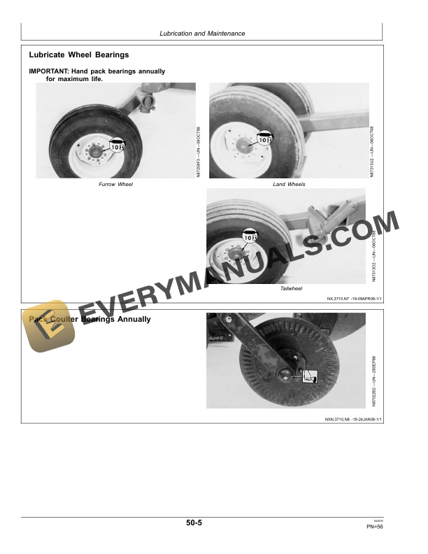
- 1.9.11. Lubricate Wheel Bearings
- 1.9.12. Pack Coulter Bearings Annually
- 1.9.13. Lubricate Adjustable Force Cushion Coulters
- 1.9.14. Lubricate SpringReset Standards
- 1.9.15. Lubricate SafetyTrip Standards
- 1.9.16. Lubricate Toggle Pins
- 1.10. Troubleshooting
- 1.10.1. Troubleshooting
- 1.11. Service
- 1.11.1. Using Safe Service Procedures
- 1.11.2. Keep Service Area Clean
- 1.11.3. Metric Bolt and Screw Torque Values
- 1.11.4. Unified Inch Bolt and Screw Torque Values
- 1.11.5. Face Seal Fittings Assembly and InstallationAll Pressure Applic
- 1.11.6. Metric Face Seal and ORing Stud End Fitting Torque ChartStanda
- 1.11.7. SAE Face Seal and ORing Stud End Fitting Torque ChartStandard
- 1.11.8. Discarded Tires
- 1.11.9. Service Tires Safely
- 1.11.10. Repair Tire
- 1.11.11. Checking Tire Pressure
- 1.11.12. Checking Wheel Bolts And Bearings
- 1.11.13. Protecting Plow Bottoms
- 1.11.14. Checking Shin And Trash Board
- 1.11.15. Landsides
- 1.11.16. Inspecting Coulters
- 1.11.17. Replacing Coulter Shear Bolts
- 1.11.18. Replacing Cushion Coulter Shear Bolts
- 1.11.19. SafetyTrip Standards
- 1.11.20. Prevent Hydraulic System Contamination
- 1.11.21. Removing Hydraulic Cylinders
- 1.11.22. Installing and Bleeding Cylinders
- 1.12. Storage
- 1.12.1. Preparing For Storage
- 1.12.2. Removing From Storage
- 1.13. Specifications
- 1.13.1. Download Force On Tractor Drawbar
- 1.13.2. Recommended Tractors
- 1.13.3. General
- 1.13.4. Serial Number
- 1.14. John Deere Service Literature Available
- 1.14.1. Technical Information
- 1.15. John Deere Service Keeps You on Job
- 1.15.1. John Deere Is At Your Service
- 2. Page Number
- 2.1. Section 05
- 2.2. Section 10
- 2.3. Section 15
- 2.4. Section 20
- 2.5. Section 25
- 2.6. Section 30
- 2.7. Section 35
- 2.8. Section 40
- 2.9. Section 45
- 2.10. Section 50
- 2.11. Section 55
- 2.12. Section 60
- 2.13. Section 65
- 2.14. Section 70