Description
-
Model List:
- 600 Series Rigid and Flex Cutting Platforms
- 1. Introduction
- 1.1. Foreword
- 1.2. A Message to Our Customers
- 1.3. Intended Use
- 1.4. Trademarks
- 2. Identification View
- 2.1. Identification View
- 3. Safety Features
- 3.1. Header Safety Features
- 3.2. Recognize Safety Information
- 3.3. Understand Signal Words
- 3.4. Follow Safety Instructions
- 3.5. French and Spanish Safety Signs and Operators Manual
- 3.6. Replace Safety Signs
- 3.7. Operator Ability
- 3.8. Ballasting for Safe Ground Contact
- 3.9. Parking and Leaving the Machine
- 3.10. Prepare for Emergencies
- 3.11. Wear Protective Clothing
- 3.12. Stay Clear of Harvesting Units
- 3.13. Keep Hands Away From Knives
- 3.14. Use Safety Lights and Devices
- 3.15. Transport Combine with FrontEnd Equipment Attached Safely
- 3.16. Road Transport Disconnect Switch
- 3.17. Practice Safe Maintenance
- 3.18. Remove Paint Before Welding or Heating
- 3.19. Avoid Heating Near Pressurized Fluid Lines
- 3.20. Avoid Contact With Moving Parts
- 3.21. Stay Clear of Cutterbar When Rotating Auger
- 3.22. Stay Clear of Rotating Drivelines
- 3.23. Guards and Shields
- 3.24. Avoid HighPressure Fluids
- 3.25. Service Accumulator Systems Safely
- 3.26. Service Machines Safely
- 3.27. Service Belts and Chains Safely
- 3.28. Protect Against High Pressure Spray
- 3.29. Decommissioning Proper Recycling and Disposal of Fluids and Components
- 3.30. Support Machine Properly
- 3.31. Store Attachments Safely
- 4. Safety SignsExcept North America
- 4.1. Pictorial Safety Signs
- 4.2. Replace Safety Signs
- 4.3. Recognize Safety Information
- 4.4. Operators Manual
- 4.5. Hydraulic Oil and Gas Under Pressure
- 4.6. Rotating Driveline
- 4.7. Reel Safety Stops
- 4.8. Side Shield
- 4.9. Cutterbar Movement
- 4.10. Header Entanglement
- 5. Safety SignsNorth America Only
- 5.1. Safety Signs LocationFlex Platforms Only
- 6. Attaching and Detaching
- 6.1. Location of the Rear Auger Stripper Extension
- 6.2. Identification of Coupling Type
- 6.2.1. Multicoupler
- 6.2.2. MultiPoint
- 6.3. Coupling Header to CombineMulticoupler
- 6.4. Coupling Header to CombineMultiPoint
- 6.5. Removing Header from Feeder HouseMulticoupler
- 6.6. Removing Header from Feeder HouseMultiPoint
- 6.7. Unlocking Feeder House Manually
- 6.8. Location of Locking Cable Shear Screws
- 7. Transporting
- 7.1. Transporting on Trailer
- 7.2. Transporting on Combine
- 8. Operating the Platform
- 8.1. Choice of Harvesting Time
- 8.2. Cutting Platform Operation
- 8.2.1. Cutting Height
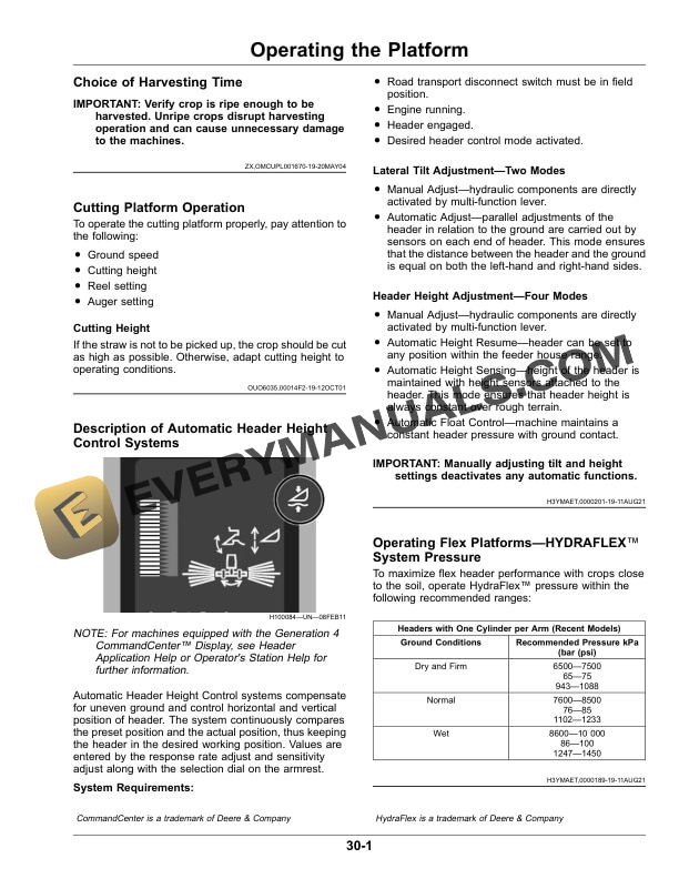
- 8.3. Description of Automatic Header Height Control Systems
- 8.4. Operating Flex PlatformsHYDRAFLEX System Pressure
- 8.5. Header Height SensingHYDRAFLEX Heads with Auxiliary Sensors
- 8.6. Wiring Harness InformationOnly for Headers Equipped with Height Sensor
- 8.6.1. General Considerations
- 8.6.2. Routing on LeftHand Side of Header
- 8.6.3. Routing on RightHand Side of Header
- 8.6.4. Lower Center Header Section Routing
- 8.7. Operating Flex Platform in Rigid Mode
- 8.8. Auxiliary Sensor Arm Operating Positions
- 8.9. Flex System Lock for Rigid Mode OperationOnly for Headers Equipped with Height Sensor
- 8.10. Operating and Servicing RequirementsOnly for Headers Equipped with Height Sensor
- 8.10.1. Active and Inactive Height Sensor Assembly Position
- 8.10.2. Lubrication
- 8.11. Checking Platform Speeds
- 8.12. Reel Operation
- 8.13. Cutting Platform Controls
- 8.14. Position Warning Lights for Field Operation
- 8.15. Combining Oats, Sorghum, Wheat, and Sunflowers in Dry Ground Conditions
- 8.16. Combining Oats, Sorghum, and Wheat in Damp or Wet Ground Conditions
- 8.17. Combining Oats, Sorghum, Barley, and Wheat in Short, Thin CropsRigid Platforms
- 8.18. Combining RiceRigid Platforms
- 8.19. Combining SoybeansFlex Platforms
- 9. Attachments and Options
- 9.1. Auger Flight Extensions (Attachment)Flex Platforms
- 9.2. Auger Speeds (Attachment)
- 9.3. Stubble Lights (Optional)Flex Platforms
- 9.4. Fine Serrated Knife (Optional)
- 9.5. Knife Assemblies with LongShort Sections (Optional)
- 9.6. Knife Drive Sheaves (Attachment)
- 9.7. HeavyDuty Wear PlatesRigid Platforms
- 9.8. Reel Position Resume (Attachment)S Series Combines
- 9.9. Short Dividers (Optional)Flex Platforms
- 9.10. Spare Knife Storage (Attachment)
- 9.11. Raised Height Skid Shoes (Optional)
- 9.12. Low Stone Dam (Attachment or Option)
- 9.13. High Stone Dam (Attachment or Option)
- 10. Calibration and Settings
- 10.1. When to Calibrate
- 10.2. Calibration Error Codes
- 10.3. Calibration Procedures
- 11. Adjustments Flex Platform
- 11.1. Adjust Platform Cutterbar/Skid Plate Tilt
- 11.2. Adjusting Head Drop Rate
- 11.3. Standard PERMAGLIDE Divider Points
- 11.4. Adjusting Standard PERMAGLIDE Divider Point Height
- 11.5. SidetoSide Adjustment of Front Section of Standard PERMAGLIDE Point
- 12. Adjustments Rigid Platform
- 12.1. Cutterbar Positions
- 12.2. Adjusting Cutterbar Fore/Aft
- 12.3. Adjusting Platform Cutterbar/Skid Plate Tilt
- 12.4. Adjusting Head Drop Rate
- 13. Adjustments Auger and Stripper
- 13.1. Auger Configuration Information Sign
- 13.2. Remove Knife Drive Belt from Drive Sheave
- 13.3. Adjusting Auger Position
- 13.4. Adjusting Auger Height
- 13.5. Adjusting Auger Fore/Aft
- 13.6. Adjusting Center Auger Finger Timing
- 13.7. Adjusting Rear Stripper
- 13.8. Adjusting Floor Stripper
- 13.9. Adjusting Auger Chain
- 14. Adjustments Reel
- 14.1. Adjust Reel Fingers
- 14.2. Adjusting Minimum Reel Height and Leveling Reel
- 14.3. Adjusting Width Between Reel Arms
- 14.4. Adjusting Reel Fore/Aft and Lift Cylinders
- 14.5. Rephase Hydraulic Reel Fore/Aft
- 14.6. Rephasing Reel Lift Cylinders
- 14.7. Bleeding the Reel Lift Cylinder System
- 14.8. Adjusting Reel Speed Ratio Sensor
- 14.9. Adjusting Reel Drive Gear
- 14.10. Adjusting Platform Height Restoring System
- 15. Lubricants
- 15.1. Gear Oil
- 15.2. Alternative and Synthetic Lubricants
- 15.3. Mixing of Lubricants
- 15.4. Lubricant Storage
- 15.5. Multipurpose Grease
- 16. Lubrication and Service
- 16.1. Lubrication Intervals Information Sign
- 16.2. Lubrication Symbols
- 16.3. Care and Maintenance of Belts
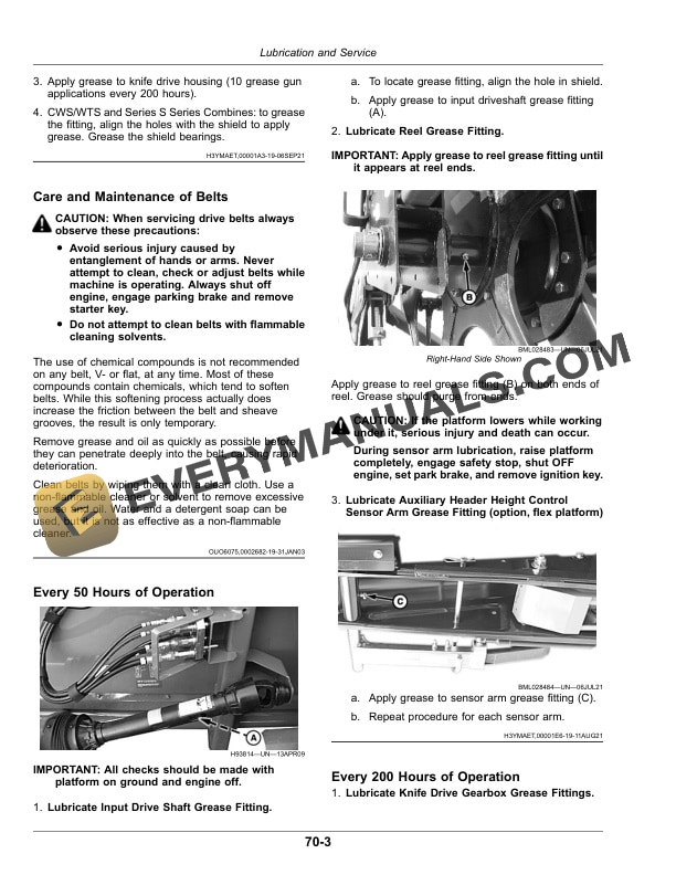
- 16.4. Every 50 Hours of Operation
- 16.5. Every 200 Hours of Operation
- 16.6. Every 400 Hours of Operation
- 17. Troubleshooting
- 17.1. Cutterbar Difficulties
- 17.2. Down and Tangled Crops Difficulties
- 17.3. Feeder House Difficulties
- 17.4. Auger Difficulties
- 17.5. Cutting Difficulties
- 17.6. Reel Difficulties
- 17.7. Hydraulic System Difficulties
- 17.8. ACTIVE HEADER CONTROL
- 18. Servicing
- 18.1. Safe Cutting Platform Operation
- 18.2. Reel Safety Stops
- 18.3. Opening and Closing Right and LeftHand Shields
- 18.4. Remove and Install Knife Drive Belt
- 18.4.1. Rigid Headers
- 18.4.2. Flex Headers
- 18.5. Adjusting Knife Drive Belt Tension
- 18.6. Replacing Cutterbar Knife
- 18.7. Knife and Knife Drive Alignment
- 18.8. Knife HoldDown Clearance
- 18.9. Replacing Knife Sections
- 18.10. Replacing Auger Fingers and Retainers
- 18.11. Stubble Light Bulb Replacement
- 18.12. Header Warning Light Bulb Replacement
- 18.13. Bleeding HydraFlex SystemFlex Headers
- 19. Storage
- 19.1. End of Season Service
- 19.2. Beginning of Season Service
- 19.3. Prepare Machine for Storage
- 20. Specifications
- 20.1. SpecificationsRigid Platforms
- 20.2. Dimensions/WeightsRigid Cutting Platforms
- 20.3. SpecificationsFlex Platforms
- 20.4. Dimensions/WeightsFlex Cutting Platforms
- 20.5. Metric Bolt and Screw Torque Values
- 20.6. Unified Inch Bolt and Screw Torque Values
- 20.7. Machine Design Life
- 21. Serial Number
- 21.1. Identification Numbers
- 21.2. Identification Plate
- 21.3. Keep Proof of Ownership
- 21.4. Interpreting Machine Serial Number
- 21.5. Product Identification Number
- 22. John Deere Service Literature Available
- 22.1. Technical Information
- 23. John Deere ServiceKeeps You on the Job
- 23.1. John Deere Parts
- 23.2. The Right Tools
- 23.3. WellTrained Technicians
- 23.4. Prompt Service