Description
-
Model List:
- 680 Disk Harrow
- 1. Introduction
- 1.1. Foreword
- 1.2. Identification View
- 1.3. A Message to Our Customers
- 1.4. Preliminary Checks
- 1.5. Regions and Country Versions
- 1.6. Machine Overview
- 1.7. Recognize Safety Information
- 1.8. Understand Signal Words
- 1.9. Follow Safety Instructions
- 1.10. Prepare for Emergencies
- 1.11. Wear Protective Clothing
- 1.12. Protect Against Noise
- 1.13. Practice Safe Maintenance
- 1.14. Handle Electronic Components and Brackets Safely
- 1.15. Park Machine Safely
- 1.16. Support Raised Equipment
- 1.17. Remove Paint Before Welding or Heating
- 1.18. Avoid Heating Near Pressurized Fluid Lines
- 1.19. Avoid HighPressure Fluids
- 1.20. Inspect Lift Circuit Hoses
- 1.21. Store Attachments Safely
- 1.22. Service Tires Safely
- 1.23. Decommissioning Proper Recycling and Disposal of Fluids and Components
- 1.24. Handle Chemical Products Safely
- 1.25. NonPermissible Use
- 1.26. Use Safety Lights and Devices
- 1.27. Keep Riders Off Machine
- 1.28. Observe Maximum Transport Speed
- 1.29. Use a Signal Person
- 1.30. Use a Safety Chain
- 1.31. Tow Loads Safely
- 1.32. Prepare for Transport
- 1.33. Transport Safely
- 1.34. Transport Implement Train
- 1.35. Transport Lockup Cylinder
- 1.36. Park Safely
- 2. Safety Signs
- 2.1. Safety Decals
- 3. Safety Features
- 3.1. Safety FeaturesMachines with SAE Connector
- 4. Preparing the Tractor
- 4.1. Use Tractor Operators Manual
- 4.2. Determining Tractor Requirements
- 4.3. Hydraulic Cylinder
- 4.4. Preparing Hydraulic System
- 4.5. Positioning Drawbar
- 5. Preparing the Machine
- 5.1. Drawbar Requirements
- 5.2. Check and Lubricate Machine
- 5.3. Check Tire PressureAll Tillage Machines
- 5.4. Check Wheel HardwareAll Tillage Machines
- 5.5. Adjust Scrapers
- 5.6. Turnbuckle Distance Leveling System
- 5.7. Toolbox
- 6. Attaching and Detaching
- 6.1. Use Your Tractor and Tillage Equipment Operators Manuals
- 6.2. Before Attaching Machine to Tractor
- 6.3. Attach Machine to Tractor
- 6.4. Attach Electrical Connectors
- 6.5. Position Jacks for Transport
- 6.6. Attach Safety Chain to Tractor
- 6.7. Attach Warning Light PlugMachines with SAE Connector
- 6.8. Detach from Tractor
- 7. Transporting the Machine
- 7.1. Use Safety Lights and Devices
- 7.2. Attach Warning Light PlugSAE Connector
- 7.3. Observe Maximum Transport Speed
- 7.4. Position Tractor Drawbar
- 7.5. Use a Safety Chain
- 7.6. Attach Safety Chain to Tractor
- 7.7. Tow Loads Safely
- 7.8. Prepare for Transport
- 7.9. Transport Safely
- 7.10. Transport Implement Train
- 8. Operating the Machine
- 8.1. Guidelines for Use
- 8.2. Tighten Hardware
- 8.3. Field Operating Speed
- 8.4. Attach Drawbar and Rolling Basket
- 8.5. Enable High Configuration and Prepare Work Position
- 8.6. Preparing to Operate in Field
- 8.7. Using Single Point Depth Stop Control
- 8.8. Adjusting Transport Wheel Height
- 9. Attachments
- 9.1. General
- 9.2. Hydraulic Cylinders and Hoses
- 9.3. Safety Reflector
- 9.4. Warning Lights
- 9.5. SMV Installation
- 10. Lubrication
- 10.1. Use Safe Service Procedures
- 10.2. Alternative and Synthetic Lubricants
- 10.3. Lubricant Storage
- 10.4. Lubrication Symbols
- 10.5. Beginning and End of Season
- 10.6. Lubricate Leveling Adjustment Spring Retainer
- 10.7. Lubricate Leveling Adjustment Trunnion
- 10.8. Lubricate Turnbuckle
- 10.9. Grease Fittings
- 10.10. Lubricate Wheel Bearings
- 10.11. Bearing Lubrication
- 10.12. Lubricate Bearings
- 11. Troubleshooting
- 11.1. Before Entering Field Guidelines
- 11.2. Troubleshooting
- 11.3. Troubleshooting
- 11.4. Troubleshooting
- 12. Service
- 12.1. Practice Safe Maintenance
- 12.2. Use Safe Service Procedures
- 12.3. Work in Clean Area
- 12.4. Service Machines Safely
- 12.5. Support Machine Properly
- 12.6. Avoid HighPressure Fluids
- 12.7. Replace Hydraulic Hoses
- 12.8. Tighten Hardware
- 12.9. Sharpen Sweeps and Disks
- 12.10. Metric Bolt and Screw Torque Values
- 12.11. Unified Inch Bolt and Screw Torque Values
- 12.12. Face Seal Fittings Assembly and InstallationAll Pressure Applications
- 12.12.1. Face Seal ORing to Stud End Installation
- 12.12.2. Face Seal Adjustable Stud End ORing Installation
- 12.12.3. Face Seal Straight Stud End ORing Installation
- 12.12.4. Fitting Installation
- 12.12.5. Assembly Torque
- 12.13. Metric Face Seal and ORing Stud End Fitting Torque ChartStandard Pressures
- 12.14. SAE Face Seal and ORing Stud End Fitting Torque ChartStandard Pressures
- 12.15. Service Tires Safely
- 12.16. Check Tire PressureAll Tillage Machines
- 12.17. Discard Tires Properly
- 12.18. Check Wheel Bearings
- 12.19. Wheel Arm Bearing Inspection
- 12.20. Discard Waste Oil Properly
- 12.21. Prevent Hydraulic System Contamination
- 12.22. Cleanliness
- 12.23. Replace Scrapers
- 12.24. Gang Component Diagram
- 12.25. Assemble Gang Bolt Tensioner
- 12.26. Disassemble Gangs
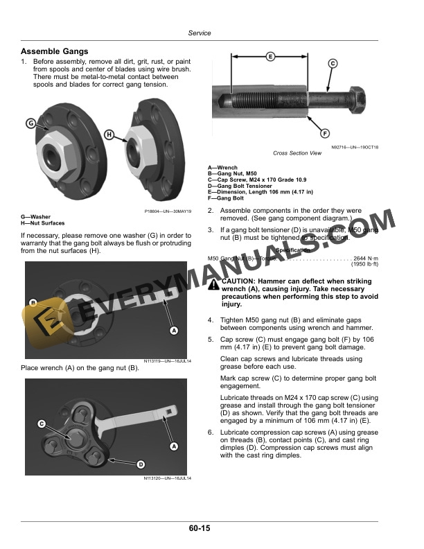
- 12.27. Assemble Gangs
- 12.28. Tighten CSpring Standards
- 12.29. Attach Gang to CSpring Standards
- 12.30. Gang Identification
- 12.31. Disk Harrow of 14 Disk Blades with spool of 279.4 mm 11
- 12.32. Disk Harrow of 14 Disk Blades with spool of 279.4 mm 11
- 12.33. Disk Harrow of 16 Disk Blades with spool of 279.4 mm 11
- 12.34. Disk Harrow of 16 Disk Blades with spool of 279.4 mm 11
- 12.35. Disk Harrow of 18 Disk Blades with spool of 279.4 mm 11
- 12.36. Disk Harrow of 18 Disk Blades with spool of 279.4 mm 11
- 12.37. Disk Harrow of 20 Disk Blades with spool of 279.4 mm 11
- 12.38. Disk Harrow of 20 Disk Blades with spool of 279.4 mm 11
- 12.39. Disk Harrow of 24 Disk Blades with spool of 279.4 mm 11
- 12.40. Disk Harrow of 24 Disk Blades with spool of 279.4 mm 11
- 12.41. Disk Harrow of 28 Disk Blades with spool of 279.4 mm 11
- 12.42. Disk Harrow of 28 Disk Blades with spool of 279.4 mm 11
- 12.43. Disk Harrow of 18 Disk Blades with spool of 228.6 mm 9
- 12.44. Disk Harrow of 18 Disk Blades with spool of 228.6 mm 9
- 12.45. Disk Harrow of 20 Disk Blades with spool of 228.6 mm 9
- 12.46. Disk Harrow of 20 Disk Blades with spool of 228.6 mm 9
- 12.47. Disk Harrow of 24 Disk Blades with spool of 228.6 mm 9
- 12.48. Disk Harrow of 24 Disk Blades with spool of 228.6 mm 9
- 12.49. Disk Harrow of 28 Disk Blades with spool of 228.6 mm 9
- 12.50. Disk Harrow of 28 Disk Blades with spool of 228.6 mm 9
- 12.51. Assembly of Disk Gang to Main Frame
- 12.52. Angle of Disk Gang to Main Frame
- 12.53. Filling Furrows
- 12.54. Adjusting Disk Depth FronttoRear
- 12.55. Changing Turnbuckle Connection
- 12.56. Tighten Scraper Tube UBolt Nuts
- 12.57. Identify Disk Blades Eligible for Warranty
- 12.58. Identify Blades Not Eligible for Warranty
- 13. Storage
- 13.1. Beginning of Season Service
- 13.2. End of Season Service
- 14. Specifications
- 14.1. Tractor PTO Power Requirements
- 14.2. Hitch Specifications
- 14.3. Machine Specifications
- 14.4. Product Identification Number
- 14.4.1. Content of Individual Positions or Group of Position Character Products Serial Number
- 15. John Deere Service Literature Available
- 15.1. Technical Information
- 15.2. John Deere Parts
- 15.3. The Right Tools
- 15.4. WellTrained Technicians
- 15.5. Prompt Service