Description
-
Model List:
- 714 Mulch Tiller
- 1. Contents
- 1.0.1. Recognize Safety Information
- 1.0.2. Understand Signal Words
- 1.0.3. Follow Safety Instructions
- 1.0.4. Spanish Safety Signs and Operators Manual
- 1.0.5. Prepare for Emergencies
- 1.0.6. Wear Protective Clothing
- 1.0.7. Practice Safe Maintenance
- 1.0.8. Handle Global Positioning Receivers and Brackets Safely
- 1.0.9. Support Raised Equipment
- 1.0.10. Remove Paint Before Welding or Heating
- 1.0.11. Avoid Heating Near Pressurized Fluid Lines
- 1.0.12. Avoid HighPressure Fluids
- 1.0.13. Check Hydraulic Hoses
- 1.0.14. Inspect Lift Circuit Hoses
- 1.0.15. Store Attachments Safely
- 1.0.16. Service Tires Safely
- 1.0.17. Dispose of Waste Properly
- 1.0.18. Handle Chemical Products Safely
- 1.0.19. Operate Safely
- 1.0.20. Use Safety Lights and Devices
- 1.0.21. Keep Riders Off Machine
- 1.0.22. Observe Maximum Transport Speed
- 1.0.23. Use a Safety Chain
- 1.0.24. Tow Loads Safely
- 1.0.25. Avoid Overhead Power Lines
- 1.0.26. Prepare for Transport
- 1.0.27. Transport Safely
- 1.0.28. Transport LockUp Valve
- 1.0.29. Do Not Fold Wings Until Machine Is Fully Raised
- 1.0.30. Park Safely
- 1.1. Safety Signs
- 1.1.1. Replace Damaged or Missing Safety Signs
- 1.1.2. Main Frame
- 1.1.3. Wing Plates
- 1.1.4. Safety Features
- 1.2. Identification View
- 1.2.1. Identification View
- 1.3. Preparing Tractor
- 1.3.1. Determining Tractor Requirements
- 1.3.2. Preparing Hydraulic System (80009000 Series Tractors)
- 1.3.3. Securing ThreePoint Hitch
- 1.3.4. Positioning Drawbar
- 1.4. Preparing Machine
- 1.4.1. Checking And Lubricating Machine
- 1.4.2. Installing Weights
- 1.4.3. Installing Hydraulic Cylinder (TwoBar Machines)
- 1.5. Attaching And Detaching
- 1.5.1. Attaching Machine Safely
- 1.5.2. Attaching Machine To Tractor
- 1.5.3. Attaching Safety Chain To Tractor
- 1.5.4. Making Proper Hose Connections
- 1.5.5. Attaching Hydraulics (80009000 And 80209020 Series Tractors)
- 1.5.6. Attaching Warning Lights
- 1.5.7. Leveling Machine (Three Bar Only)
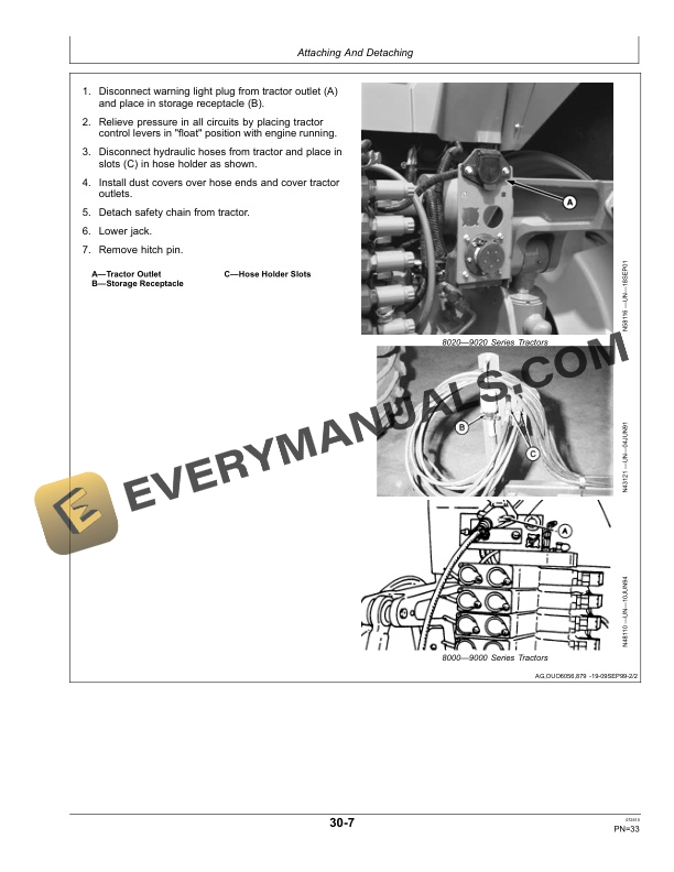
- 1.5.8. Detaching Machine From Tractor (80009000 and 80209020 Series T
- 1.6. Transporting
- 1.6.1. Following Safe Transport Procedures
- 1.6.2. Attaching Safety Chain To Tractor
- 1.6.3. Using Warning Lights And SMV
- 1.6.4. Positioning Tractor Drawbar For Transport
- 1.6.5. Positioning Jack For Transport
- 1.6.6. Locking Up Depth Control (ThreeBar Machines)
- 1.6.7. Locking Up Depth Control (TwoBar Machines)
- 1.7. Operating Machine
- 1.7.1. Operating Guidelines
- 1.7.2. Tightening Hardware
- 1.7.3. Using Operators Manual Holder
- 1.7.4. Unlocking Depth Control For Field Operation (ThreeBar Machines)
- 1.7.5. Unlocking Depth Control For Field Operation (TwoBar Machines)
- 1.7.6. Leveling Machine (TwoBar Machine)
- 1.7.7. Leveling Machine (ThreeBar Machine)
- 1.7.8. Adjusting Optional Hydraulic Cylinder Depth Control (TwoBar Mac
- 1.7.9. Adjusting Tractor Remote Cylinder Depth Control (TwoBar Machine
- 1.7.10. Setting Single Point Depth Control(ThreeBar Machines)
- 1.7.11. Adjusting DownPressure Of Disk Or Coulter Gangs
- 1.7.12. Leveling Wings (Folding Machines)
- 1.7.13. Adjusting Disk Or Coulter Gang Depth (Manual)
- 1.7.14. Adjusting Coulter Gang Depth (Hydraulic)
- 1.7.15. Adjusting Wing Lift Cylinders
- 1.7.16. Adjusting Wing Stops
- 1.7.17. Adjusting Scraper For Rigid Operation
- 1.7.18. Adjusting Scraper For SelfAdjusting Operation
- 1.7.19. Choosing Proper Tools For Soil Conditions
- 1.7.20. Replacing Twisted Shovels
- 1.7.21. Adjusting Stabilizer Wheels
- 1.8. Lubrication And Maintenance
- 1.8.1. Lubricating and Maintaining Machine Safely
- 1.8.2. Alternative and Synthetic Lubricants
- 1.8.3. Lubricant Storage
- 1.8.4. Beginning and End of Season
- 1.8.5. Lubrication Symbol
- 1.8.6. Lubrication Intervals
- 1.8.7. Lubricating Stabilizer Wheel
- 1.8.8. Lubricating Depth Control Wheels
- 1.8.9. Lubricating Coulter Gangs
- 1.8.10. Lubricating Disk Gangs
- 1.8.11. Lubricating Turnbuckle
- 1.9. Troubleshooting
- 1.9.1. Troubleshooting
- 1.9.2. Troubleshooting Drawbar Hitch Links
- 1.10. Service
- 1.10.1. Practice Safe Maintenance
- 1.10.2. Using Safe Service Procedures
- 1.10.3. Work in Clean Area
- 1.10.4. Service Machines Safely
- 1.10.5. Illuminate Work Area Safely
- 1.10.6. Support Machine Properly
- 1.10.7. Keep Service Area Clean
- 1.10.8. Replacing Ground Engaging Tools
- 1.10.9. Tighten Hardware
- 1.10.10. Metric Bolt and Screw Torque Values
- 1.10.11. Unified Inch Bolt and Screw Torque Values
- 1.10.12. Face Seal Fittings Assembly and InstallationAll Pressure Applic
- 1.10.13. Metric Face Seal and ORing Stud End Fitting Torque ChartStanda
- 1.10.14. SAE Face Seal and ORing Stud End Fitting Torque ChartStandard
- 1.10.15. Servicing Tires Safely
- 1.10.16. Discarded Tires
- 1.10.17. Checking Tire Pressure
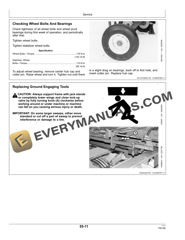
- 1.10.18. Checking Wheel Bolts And Bearings
- 1.10.19. Replacing Ground Engaging Tools
- 1.10.20. Checking Torque On SpringReset Standards
- 1.10.21. Checking Torque On TRUDEPTH Standards
- 1.10.22. Using Special Socket WrenchAttachment
- 1.10.23. Checking Torque On Disk And Coulter Gang Hardware
- 1.10.24. Tightening Gang Bolts
- 1.10.25. Gang Bolt Wrenches
- 1.10.26. Hydraulic System Quick Check For Tillage Machines Using Single P
- 1.10.27. Checking Depth Control Cylinders For Internal Leakage
- 1.10.28. Parallel/Series Hydraulic Depth Control Diagnosis Analyzing Test
- 1.10.29. Preventing Hydraulic System Contamination
- 1.10.30. Removing Hydraulic Cylinders
- 1.10.31. Bleeding Depth Control Cylinders
- 1.10.32. Installing And Bleeding Wing Fold Cylinders
- 1.10.33. Identifying Disk Or Coulter Blades Eligible For Warranty
- 1.10.34. Identifying Disk Or Coulter Blades Not Eligible For Warranty
- 1.10.35. Replacing Scraper Blades
- 1.10.36. Standard Spacing Diagram1.9 M And 2.7 M (6 Ft 3 In. And 8 Ft 9
- 1.10.37. Standard Spacing Diagram1.9 M (6 Ft 3 In.) Model With Coulter G
- 1.10.38. Standard Spacing Diagram2.7 M (8 Ft 9 In.) Model With Coulter G
- 1.10.39. Standard Spacing Diagram3.4 M (11 Ft 3 In.) Models With Coulter
- 1.10.40. Standard Spacing Diagram3.4 M And 4.2 M (11 Ft 3 In. And 13 Ft
- 1.10.41. Standard Spacing Diagram3.4 M And 4.2 M (11 Ft 3 In. And 13 Ft
- 1.10.42. Standard Spacing Diagram3.4 M And 4.2 M (11 Ft 3 In. And 13 Ft
- 1.10.43. Standard Spacing Diagram4.9 M (16 Ft 3 In.) Rigid Models With C
- 1.10.44. Standard Spacing Diagram4.9 M (16 Ft 3 In.) Rigid Models With D
- 1.10.45. Standard Spacing Diagram5.7 And 6.5 M (18 Ft 9 In. And 21 Ft 3
- 1.11. Storage
- 1.11.1. Preparing Machine For Storage
- 1.11.2. Removing Machine From Storage
- 1.12. Specifications
- 1.12.1. Hitch Specifications
- 1.12.2. Download Force On Tractor Drawbar
- 1.12.3. Tractor Horsepower Recommendations
- 1.12.4. General Information
- 1.12.5. Hydraulic Requirements
- 1.12.6. Transport Width And Height
- 1.12.7. Machine Weight (Base Machine)
- 1.12.8. Tire Specifications
- 1.12.9. Keep Proof of Ownership
- 1.12.10. Record Product Identification Number ( P.I.N.)
- 1.12.11. Keep Machines Secure
- 1.13. John Deere Service Literature Available
- 1.13.1. Technical Information
- 1.14. John Deere Service Keeps You On the Job
- 1.14.1. John Deere Is At Your Service
- 2. Page Number
- 2.1. Section 05
- 2.2. Section 10
- 2.3. Section 15
- 2.4. Section 20
- 2.5. Section 25
- 2.6. Section 30
- 2.7. Section 35
- 2.8. Section 40
- 2.9. Section 45
- 2.10. Section 50
- 2.11. Section 55
- 2.12. Section 60
- 2.13. Section 65