

Description
-
Model List:
- 2210 Field Cultivator AccuDepth Control System
- 2410 Chisel Plow AccuDepth Control System
- 1. Contents
- 1.0.1. Recognize Safety Information
- 1.0.2. Understand Signal Words
- 1.0.3. Follow Safety Instructions
- 1.0.4. Operate Safely
- 1.0.5. Observe Maximum Transport Speed
- 1.0.6. Keep Riders Off Machine
- 1.0.7. Prepare for Emergencies
- 1.0.8. Wear Protective Clothing
- 1.0.9. Use Safety Lights and Devices
- 1.0.10. Use a Safety Chain
- 1.0.11. Transport Safely
- 1.0.12. Tow Loads Safely
- 1.0.13. Practice Safe Maintenance
- 1.0.14. Support Raised Equipment
- 1.0.15. Avoid HighPressure Fluids
- 1.0.16. Check Hydraulic Hoses
- 1.0.17. Park Safely
- 1.0.18. Store Attachments Safely
- 1.0.19. Warnings for Machines Equipped with Computer Controlled Systems
- 1.1. System Components
- 1.1.1. Basic Operation of AccuDepth System
- 1.1.2. Monitor and Control System
- 1.1.3. Monitor
- 1.2. GreenStar Harness Installation
- 1.2.1. Install GreenStar Harness (John Deere 8000/9000 Series Tractors)
- 1.2.2. Install Monitor Bracket
- 1.2.3. Communication System Terminator
- 1.2.4. Replacing Eproms
- 1.3. Addon Valve
- 1.3.1. Addon Package
- 1.3.2. Route Harness To Rear Display Mount
- 1.3.3. Install Monitor Bracket
- 1.3.4. Install SCV
- 1.3.5. Route Harness Outside Tractor
- 1.3.6. Install DEUTSCH Connector Bracket
- 1.3.7. Install Addon Valve
- 1.3.8. Locking SCV
- 1.3.9. Changing From Addon Valve System to John Deere 8000/9000 Series Tractor
- 1.3.10. Change From John Deere 8000/9000 Series Tractor to Addon Valve System (Addon Valve System Installed)
- 1.4. AccuDepth Display
- 1.4.1. Attaching
- 1.4.2. Detaching
- 1.4.3. AccuDepth Display Information
- 1.4.4. RUN Mode
- 1.4.5. SETUP Mode
- 1.4.6. Setting UnitsofMeasure
- 1.4.7. Calibrate AccuDepth System
- 1.4.8. Setting Values for Flick Operations
- 1.4.9. Setting Tool Engaged Depth
- 1.4.10. Display StartUp
- 1.4.11. Adjusting Machine Depth
- 1.4.12. Preparing to Operate Machine in Field
- 1.4.13. Tillage Tool RUN Mode
- 1.4.14. Leveling Machine FrameSideToSide (Setting Zero Depth)
- 1.4.15. Adjusting Center Offset
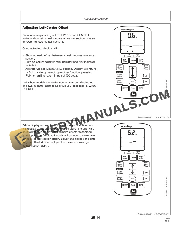
- 1.4.16. Adjusting LeftCenter Offset
- 1.4.17. Adjusting RightCenter Offset
- 1.4.18. Adjusting Wing Offset
- 1.4.19. Adjusting Level Display
- 1.4.20. Adjusting Depth Display
- 1.4.21. Setting Lower and Upper Limits
- 1.4.22. Operating in Field
- 1.4.23. Audio Alarm Signals
- 1.4.24. INFO (Information) Mode
- 1.4.25. Error Codes (INFO Mode)
- 1.5. GreenStar Display
- 1.5.1. SETUP Mode
- 1.5.2. Changing Readout Language and UnitsofMeasure
- 1.5.3. SETUP ModeRUN Page Layout
- 1.5.4. RUN Mode
- 1.5.5. Display StartUp
- 1.5.6. Tillage Tool SETUP Mode, Overview
- 1.5.7. Calibrate AccuDepth System
- 1.5.8. Setting Values for Flick Operations
- 1.5.9. Setting Tool Engaged Depth
- 1.5.10. Adjusting Machine Depth
- 1.5.11. Preparing to Operate Machine in Field
- 1.5.12. Tillage Tool Run Mode
- 1.5.13. Leveling Machine FrameSideToSide (Setting Zero Depth)
- 1.5.14. Setting Lower and Upper Limits
- 1.5.15. Operating in Field
- 1.5.16. Audio Alarm Signals
- 1.5.17. Frame Indicator Bars
- 1.5.18. Warnings, Cautions and Advisories
- 1.5.19. Stop Warning Messages and Reactions
- 1.5.20. Caution Warning Messages and Reactions
- 1.5.21. Information Warning Messages and Reactions
- 1.5.22. Informative Caution Messages and Reactions
- 1.5.23. INFO (Information) Mode
- 1.5.24. Voltage Check
- 1.5.25. Error and Fault Codes
- 1.5.26. Tillage Tool INFO (Information) Mode
- 1.5.27. Tillage Tool Problem Codes and Descriptions
- 1.5.28. Troubleshooting GreenStar Display
- 1.6. GS2 Display
- 1.6.1. SETUP Mode
- 1.6.2. Calibrate AccuDepth System
- 1.6.3. Leveling Machine FramesSideToSide (Setting Zero Depth)
- 1.6.4. Preparing to Operate Machine in Field
- 1.6.5. Setting Lower and Upper Limits
- 1.6.6. Operating in Field
- 1.6.7. Messages
- 1.6.8. Audio Alarm Signals
- 1.6.9. Warnings, Cautions and Advisories
- 1.6.10. Recent Problems
- 1.6.11. Diagnostics
- 1.6.12. Warning Screens
- 1.6.13. Error and Fault Codes
- 1.6.14. Tillage Tool Problem Codes and Descriptions
- 1.6.15. Troubleshooting GreenStar Display
- 1.7. Overriding Electronic Depth Control
- 1.7.1. Overriding Electronic Depth Control
- 1.7.2. Operating With Wing Potentiometer or Proportional Valve Failure
- 1.7.3. WingFold Operation In Mechanical Override Mode
- 1.8. AccuDepth Troubleshooting
- 1.8.1. Troubleshooting Monitor Problems
- 1.8.2. Troubleshooting Display and Standard Monitor/Control System(s)
- 1.8.3. Troubleshooting Display, Standard Monitor/Control and Optional Monitoring System(s) Flow Chart 1
- 1.8.4. Troubleshooting Machine
- 1.9. ServiceMachine
- 1.9.1. Warnings for Machines Equipped with Computer Controlled Systems
- 1.9.2. Using Safe Service Procedures
- 1.9.3. Checking Depth Control Hydraulic System
- 1.9.4. Preventing Hydraulic System Contamination
- 1.9.5. Checking Controller Harness Fuses
- 1.10. ServiceElectronic Depth Control
- 1.10.1. Warnings for Machines Equipped with Computer Controlled Systems
- 1.10.2. Replacing Potentiometers
- 1.10.3. Replacing Solenoids
- 1.10.4. ElectroHydraulic System DiagramActive Depth Control
- 1.10.5. Electromagnetic Interference (EMI)
- 1.10.6. Check Communication Cable(s)
- 1.10.7. Basic Informational Warnings for Machines Equipped with Computer Controlled Systems
- 1.10.8. Checks Before Testing
- 1.11. Specifications
- 1.11.1. Record Serial NumbersMonitor and Control Components
- 1.12. John Deere Service Literature Available
- 1.12.1. Technical Information
- 1.13. John Deere Service Keeps You On the Job
- 1.13.1. John Deere Is At Your Service
- 2. Page Numbers
- 2.1. Section 05




