Description
-
Model List:
- Hagie Nitrogen Tool Bar
- 1. Introduction
- 1.1. Foreword
- 1.1.1. PreDelivery
- 1.1.2. Delivery
- 1.1.3. AfterSale
- 1.1.4. Owner Register
- 1.2. Recognize Safety Information
- 1.3. Understand Signal Words
- 1.4. Follow Safety Instructions
- 1.5. French and Spanish Safety Signs and Operators Manual
- 1.6. Wear Protective Clothing
- 1.7. Protect Against Noise
- 1.8. Practice Safe Maintenance
- 1.9. Avoid Backover Accidents
- 1.10. Park Machine Safely
- 1.11. Remove Paint Before Welding or Heating
- 1.12. Avoid Heating Near Pressurized Fluid Lines
- 1.13. Avoid HighPressure Fluids
- 1.14. Decommissioning Proper Recycling and Disposal of Fluids and Components
- 1.15. Handle Chemical Products Safely
- 1.16. Use Proper Tools
- 1.17. Work In Ventilated Area
- 1.18. Handling Batteries Safely
- 1.19. Remove Accumulated Crop Debris
- 1.20. Using Compressed Air For Cleaning
- 1.21. Maintain a Safe Area Around the Machine
- 1.22. Operator Ability
- 1.23. Observe Road Traffic Regulations
- 1.24. Check Machine Safety
- 1.25. Working Area
- 1.26. Before Operating
- 1.27. Operate Safely
- 1.28. Use Safety Lights and Devices
- 1.29. Keep Riders Off Machine
- 1.30. Instructional Seat
- 1.31. Use Steps and Handholds Correctly
- 1.32. Use Seat Belt Properly
- 1.33. Use Caution On Hillsides
- 1.34. Transport and Operate Safely
- 1.35. Transporting Machine Using Trailer
- 1.36. Prevent Machine Runaway
- 1.37. Handle Fuel SafelyAvoid Fires
- 1.38. Prepare for Emergencies
- 1.39. In Case of Fire
- 1.40. Handle Agricultural Chemicals Safely
- 1.41. Avoid Exposure To Chemicals
- 1.42. Clean Vehicle of Hazardous Chemicals, Including Pesticides
- 1.43. NonPermissible Use
- 1.44. Emergency Exit
- 2. Safety Signs
- 2.1. Replace Safety Signs
- 2.2. Chemical Exposure Decal
- 2.3. Agricultural Chemicals Decal
- 2.4. Tank Decal
- 2.5. Hydraulic Oil Under Pressure Decal
- 2.6. Attachment Decal
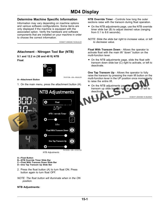
- 3. MD4 Display
- 3.1. Determine Machine Specific Information
- 3.2. Attachment Nitrogen Tool Bar (NTB)
- 3.2.1. and 12.2 m (30 and 40 ft) NTB
- 4. Operate the NTB
- 4.1. Service and Operate Chemical Sprayers Safely
- 4.2. Avoid Exposure To Chemicals
- 4.3. Before Field Operation
- 4.4. Field Operation
- 4.5. Float Operation
- 4.5.1. Spray System Master Switch (Default Setting)
- 4.5.2. Main Lift Switch (Default Setting)
- 4.5.3. Float Adjustments
- 4.6. Attachment Headlights
- 4.6.1. Operating the Attachment Headlights
- 4.6.2. Adjusting the Attachment Headlights
- 5. and 12.2 m (30 and 40 ft) NTB
- 5.1. NTB Unfold/Fold
- 5.1.1. Unfolding/Folding the NTB Attachment
- 5.1.2. Adjusting the Main Fold Sections
- 5.2. Gauge Wheel Adjustment
- 5.3. Coulter Adjustment
- 5.4. Lift Arm Pin Adjustment
- 6. QuickTach
- 6.1. Connecting/Disconnecting the NTB Attachment
- 6.1.1. Installing the Adapter Weldment
- 6.1.2. Connecting the NTB
- 6.1.3. Disconnecting the NTB
- 7. Lubrication and Maintenance
- 7.1. Clean Vehicle of Hazardous Chemicals, Including Pesticides
- 7.2. Prevent Hydraulic System Contamination
- 7.3. Dispose of Waste Properly
- 7.4. Service Intervals
- 7.5. Check Hydraulic Oil LevelDaily
- 7.6. Lubricate Fold PointsWeekly
- 7.7. Lubricate Lift Arm/Lift Cylinder Pin Grease PointsAs Required
- 7.8. Inspect Hydraulic HosesAs Required
- 7.9. Inspect NTB Structure200 Hours
- 7.10. Clean NTB and Coat Exposed SurfacesAnnually
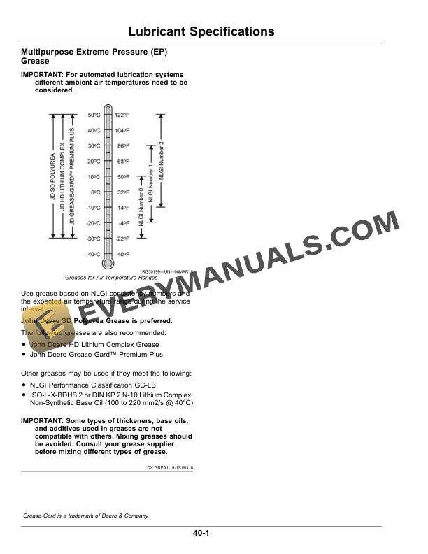
- 8. Lubricant Specifications
- 8.1. Multipurpose Extreme Pressure (EP) Grease
- 9. Storage
- 9.1. Service and Operate Chemical Sprayers Safely
- 9.2. Avoid Exposure To Chemicals
- 9.3. Clean Vehicle of Hazardous Chemicals, Including Pesticides
- 9.4. Recommended Cleaners And Coatings
- 9.5. Prepare NTB for Storage
- 9.6. Remove NTB from Storage
- 10. Transporting
- 10.1. Transporting Machine with an Attachment
- 10.1.1. Loading
- 11. Specifications
- 11.1. Specifications
- 11.2. Dimensions
- 11.3. Unified Inch Bolt and Screw Torque Values
- 11.4. Metric Bolt and Screw Torque Values
- 11.5. Face Seal Fittings Assembly and InstallationAll Pressure Applications
- 11.5.1. Face Seal ORing to Stud End Installation
- 11.5.2. Face Seal Adjustable Stud End ORing Installation
- 11.5.3. Face Seal Straight Stud End ORing Installation
- 11.5.4. Fitting Installation
- 11.5.5. Assembly Torque
- 11.6. Metric Face Seal and ORing Stud End Fitting Torque ChartStandard Pressures
- 11.7. Metric Face Seal and ORing Stud End Fitting Torque ChartHighPressure Applications
- 11.8. SAE Face Seal and ORing Stud End Fitting Torque ChartStandard Pressures
- 11.9. SAE Face Seal and ORing Stud End Fitting Torque ChartHigh Pressure Applications
- 11.10. Four Bolt Flange Fittings Assembly and InstallationAll Pressure Applications
- 11.11. SAE Four Bolt Flange Cap Screw Torque ValuesStandard Pressure Applications
- 11.12. SAE Four Bolt Flange Cap Screw Torque ValuesHigh Pressure Applications
- 11.13. External Hexagon Port Plug Torque Chart
- 11.14. Identification
- 11.15. Product Warranty
- 12. John Deere Service Literature Available
- 12.1. Technical Information
- 13. John Deere Service Keeps You On The Job
- 13.1. John Deere Is At Your Service