Description
-
Model List:
- HD200 SelectSpray Attachment For ProGator
- HD300 SelectSpray Attachment For ProGator
- 1. Introduction
- 1.1. Thank You for Purchasing a John Deere Product
- 1.2. Using Your Operators Manual
- 1.3. Machine Use
- 1.4. Special Messages
- 1.5. Service Literature
- 1.5.1. Order Service Parts Online
- 2. Contents
- 3. Product Identification
- 3.1. Product Compatibility
- 3.2. Record Identification Numbers
- 4. Safety Labels Text
- 4.1. Safety Label Location
- 4.2. Understanding the Machine Safety Labels
- 4.2.1. French or Spanish Safety Labels and Operators Manual
- 4.3. WARNING
- 4.4. WARNING
- 4.5. CAUTION
- 4.6. WARNING
- 4.7. CAUTION
- 4.8. WARNING
- 5. Safety Labels NoText
- 5.1. Safety Label LocationSprayer Tank
- 5.2. Safety Label LocationSpray Booms (5.5 m (18 ft.)
- 5.3. Safety Label LocationSpray Booms (4.66.4 m (1521 ft.)
- 5.4. Understanding the Machine Safety Labels without Text
- 5.5. Avoid Injury From Drinking Water
- 5.6. Avoid Injury From Chemical Hazards
- 5.7. Do Not Enter Tank
- 5.8. Read Operators Manual
- 5.9. Avoid Injury From Crushing
- 5.10. Avoid Injury From Moving Parts
- 5.11. Read Operators Manual, Avoid Moving Parts, Keep Bystanders Away
- 5.12. Avoid Injury From Moving Boom
- 5.13. Avoid Injury From Boom Swing Area
- 5.14. Read Safety in Machine Operators Manual
- 5.15. Operate Sprayer Safely
- 5.16. Parking Safely
- 5.17. Mix and Handle Chemicals Safely
- 5.18. Read Chemical Container Label
- 5.19. Handle Chemical Products Safely
- 5.20. Practice Safe Maintenance
- 5.21. Wear Appropriate Clothing
- 5.22. Avoid High Pressure Fluids
- 5.23. Dispose of Chemicals Properly
- 5.24. Handling Waste Product and Chemicals
- 6. Preparing Vehicle
- 6.1. Preparing the Machine
- 6.1.1. Machine Requirements
- 6.1.2. Prepare for Assembly
- 6.2. Controller Mount Bracket Kit Components
- 6.3. Tank Components
- 6.4. Electrical Components
- 6.5. Pump and Hydraulic Components
- 6.6. Personal Wash Tank Components
- 6.7. Install Control Box
- 6.7.1. Install Brackets
- 6.7.2. Install Control Box
- 6.8. Install Cylinder Support Bracket (HD300)
- 6.9. Install Sprayer
- 6.10. Install Power Harness
- 6.11. Install Console Wire Harness
- 6.12. Install Sprayer Tank Components
- 6.12.1. Tank Drain Hose
- 6.12.2. Personal Wash Tank Hose
- 6.13. Connect Sprayer Main Harness to Control Box
- 6.14. Connect Rear Wiring Harness
- 6.15. Install Frame Clamps
- 6.15.1. Installing Frame Clamps to Sprayer
- 6.15.2. Securing Sprayer to Frame
- 7. Component Overview
- 7.1. Solution Tank
- 7.1.1. Solution Tank Diagram
- 7.2. Manifold (Valve Stack)
- 7.2.1. Manifold Diagram
- 7.2.2. Centrifugal Pump Diagram
- 7.2.3. Diaphragm Pump Diagram
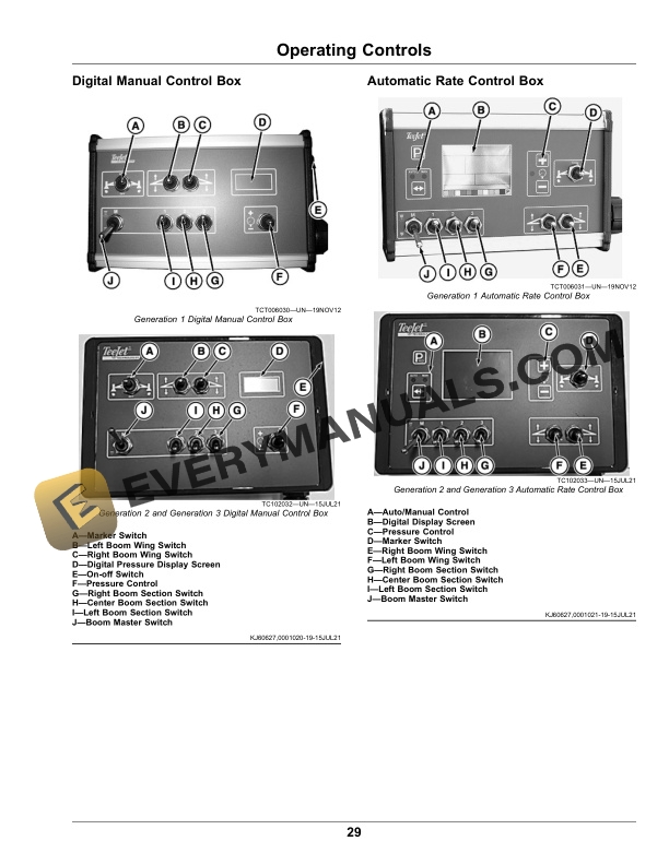
- 8. Operating Controls
- 8.1. Digital Manual Control Box
- 8.2. Automatic Rate Control Box
- 9. Operating
- 9.1. Spray Tip Operation
- 9.2. Spray Tip Selection
- 9.3. Flood Style Spray Tip
- 9.3.1. Nozzle Dimensions
- 9.4. Ultra LowDrift Style Spray Tip
- 9.4.1. Nozzle Dimensions
- 9.5. Flat Fan Style Spray Tip
- 9.5.1. Nozzle Dimensions
- 9.6. Using Digital Manual Control Box
- 9.7. Using Automatic Rate Control Box
- 9.7.1. Area / Volume Display Feature
- 9.7.2. Tank Volume Feature
- 9.7.3. Boost Mode
- 9.7.4. Sensor Alarms
- 9.7.5. User Programmable Tip
- 9.7.6. Power On Controller
- 9.7.7. Power Off Controller
- 9.8. Configuring Automatic Rate Control Box
- 9.9. Automatic Rate Controller Calibration
- 9.9.1. Speed Sensor
- 9.9.2. Pressure Sensor
- 9.9.3. Flow Meter
- 9.10. FLO and PRS Regulation
- 9.10.1. FLO Regulation Mode
- 9.10.2. PRS Regulating Mode
- 9.11. Programming Application Rate with Automatic Rate Control Box
- 9.12. Operating the Sprayer
- 9.12.1. Stopping the Sprayer
- 9.12.2. Pump Use
- 9.13. Using the Personal Wash Tank
- 9.14. Filling and Draining Sprayer Tank
- 9.14.1. Filling the Tank
- 9.14.2. Draining the Tank
- 9.15. Using ThreeWay Valve
- 9.16. Using the Agitator
- 9.17. Adjusting Throttling Valves
- 9.18. Setting System Relief Pressure (Diaphragm Pump Only)
- 9.19. Using Boom Wings
- 9.20. Using Boom Wing Extensions (4.6/6.4 m (15/21 ft) Boom Only)
- 9.21. Adjust Boom Height
- 9.22. Adjust Boom Wing Level
- 9.23. Raising and Lowering Sprayer
- 9.24. Transporting
- 10. Removing and Storing
- 10.1. Prepare Machine for Removal
- 10.2. Disconnect Hydraulic Hoses
- 10.3. Disconnect Rear Wiring Harness
- 10.4. Removing Sprayer Without Support Stands
- 10.5. Removing Sprayer With Optional Support Stands
- 10.6. Storing Safety
- 10.7. Winterization and Storage
- 10.7.1. Sprayer
- 10.7.2. Foam Marker (If Equipped)
- 10.7.3. Hose Reel (If Equipped)
- 10.7.4. Personal Wash Tank
- 10.8. Removing From Storage
- 10.8.1. Sprayer
- 10.8.2. Foam Marker (If equipped)
- 10.8.3. Personal Wash Tank
- 10.9. Remove and Store Control Box
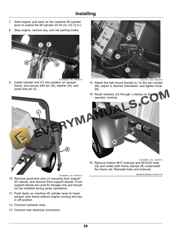
- 11. Installing
- 11.1. Installing Sprayer on Machine Without Optional Support Stands
- 11.2. Installing Sprayer on Machine With Optional Support Stands
- 12. Optional Attachments and Kits
- 12.1. Using Eductor
- 12.1.1. Operating and Transport Positions
- 12.1.2. Startup
- 12.1.3. Loading Chemicals into Hopper
- 12.1.4. Loading Chemical with Optional Suction Lance
- 12.1.5. Shutdown
- 12.2. Using Foam Marker
- 12.2.1. Operating Foam Marker
- 12.2.2. Adjusting Foam Marker
- 12.2.3. Preparing Foam Marker Solution
- 12.2.4. Selecting Concentrate
- 12.2.5. Mixing Solution
- 12.3. Using Manual and Electric Hose Reels
- 12.4. Using Rinse Tank
- 12.4.1. Filling Rinse Tank
- 12.4.2. Operating
- 13. Service
- 13.1. Service Intervals Standard Equipment
- 13.1.1. Before Each Use
- 13.1.2. After Each Use
- 13.1.3. As Needed
- 13.1.4. Annually
- 13.2. Service Intervals Optional Equipment
- 13.2.1. After Each Use
- 13.2.2. As Needed
- 13.2.3. Hours
- 13.2.4. Hours
- 13.2.5. Annually
- 13.2.6. Order Service Parts Online
- 13.3. Cleaning the Sprayer
- 13.4. Servicing the Inline Strainer
- 13.5. Verifying Sprayer Output
- 13.6. Checking Main Circuit Breaker
- 13.7. Checking Fuses and Boom Wing Actuator Circuit Breaker
- 13.8. Adjusting Boom Wing Spring Tension
- 13.9. Lubricating Boom Wing Pivots
- 13.10. Inspecting and Cleaning Vented Fill Covers
- 13.10.1. Sprayer Tank Fill Cover
- 13.10.2. Personal Wash and Foam Marker Tanks
- 13.11. Servicing Foam Marker Kit
- 13.11.1. Foam Solution Pump
- 13.11.2. Foam Solution Strainer
- 13.11.3. Air Line Check Valve
- 13.11.4. Foamhead Check Valves
- 13.11.5. Foamhead Cleaning
- 13.11.6. Winterization
- 13.12. Lubricating Ground Wheels
- 13.13. Lubricating Jack Stands
- 13.14. Servicing Hose Reel
- 13.14.1. Lubricating Electric Hose Reel
- 13.14.2. Lubricating Manual Hose Reel
- 13.14.3. Adjusting Tension Brake
- 13.15. Servicing the Diaphragm Pump
- 13.15.1. Valve Inspection and Replacement
- 13.15.2. Accumulator Diaphragm Replacement
- 13.15.3. Pump Diaphragm Replacement
- 13.15.4. Winterization
- 13.16. Installing a Test Flow Meter
- 13.17. Installing a Test Pressure Gauge
- 14. Troubleshooting
- 14.1. Using Troubleshooting Chart
- 14.2. SelectSpray HD200 HD300
- 15. Specifications
- 15.1. Optional Equipment
- 15.1.1. Foam Maker
- 15.1.2. Ground Plane Wheel
- 15.1.3. Hose Reel
- 15.2. Nozzle Flow Rate
- 15.3. Diaphragm Pump Performance Chart
- 15.4. Centrifugal Pump Performance Chart
- 16. John Deere Quality Statement
- 16.1. John Deere Quality