Description
-
Model List:
- Orthman 8×2 Twin Row Planters
- 1. Contents
- 1.0.1. Safety Features
- 1.0.2. Recognize Safety Information
- 1.0.3. Understand Signal Words
- 1.0.4. Follow Safety Instructions
- 1.0.5. Prevent Machine Runaway
- 1.0.6. Operate the Machine Safely
- 1.0.7. Keep Riders Off Machine
- 1.0.8. Avoid TipOvers
- 1.0.9. Prepare for Emergencies
- 1.0.10. Wear Protective Clothing
- 1.0.11. Handle Agricultural Chemicals Safely
- 1.0.12. Use Safety Lights and Devices
- 1.0.13. Light Enhancement Module
- 1.0.14. Replace Safety Signs
- 1.0.15. Transport Safely
- 1.0.16. Tow Loads Safely
- 1.0.17. Observe Maximum Transport Speed
- 1.0.18. Service Machine Safely
- 1.0.19. Practice Safe Maintenance
- 1.0.20. Remove Paint Before Welding or Heating
- 1.0.21. Avoid Heating Near Pressurized Fluid Lines
- 1.0.22. Avoid HighPressure Fluids
- 1.0.23. Store Attachments Safely
- 1.0.24. Dispose of Waste Properly
- 1.1. Safety Signs
- 1.1.1. Safety Signs
- 1.2. Information Signs
- 1.2.1. Information Signs
- 1.3. Preparing Tractor
- 1.3.1. Use Your Tractor Operators Manual
- 1.3.2. Tractor Requirements
- 1.3.3. Check Tractor Hydraulic System
- 1.3.4. Low Pressure Case Drain Connection
- 1.4. Preparing Machine
- 1.4.1. Support Machine Before Service
- 1.4.2. Prior to Use
- 1.4.3. Check Tire Inflation
- 1.4.4. Tightening Wheel Bolts
- 1.5. Attaching Machine
- 1.5.1. Use Your Tractor Operators Manual
- 1.5.2. CCS Fan and VacuMeter Motor (Case) Drain Requirements
- 1.5.3. VacuMeter Hydraulic Motor and Variable Rate Drive Return Coupler
- 1.5.4. Warning Lights and Slow Moving Vehicle Emblem(Style A)
- 1.5.5. Attach Machine to Tractor
- 1.5.6. Attaching Warning Light Harness
- 1.5.7. Connect SeedStar Monitor Harness
- 1.5.8. Check Hydraulic System
- 1.5.9. Hydraulic Connection Recommendations
- 1.5.10. Adjust Frame Height
- 1.5.11. Level the Machine
- 1.6. Detaching Machine
- 1.6.1. Roadway Transport Safety
- 1.6.2. Detach Machine From Tractor
- 1.6.3. Depressurize Pneumatic Down Force System
- 1.7. Operating Machine
- 1.7.1. General
- 1.7.2. How to Operate VacuMeter Hydraulic System
- 1.7.3. Raise and Lower Machine
- 1.7.4. Set Planting Depth
- 1.7.5. Setting Closing Wheel Down Force
- 1.7.6. Filling Seed Hoppers
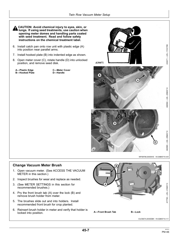
- 1.8. Twin Row Vacuum Meter Setup
- 1.8.1. Vacuum Meter Operating Characteristics
- 1.8.2. Meter Settings
- 1.8.3. Variable Rate Drive Chain Routing and Replacement
- 1.8.4. Adjust HighLow Drive Range (Variable Rate Drive Machines Only)
- 1.8.5. Access The Vacuum Meter
- 1.8.6. Change Vacuum Meter Brush
- 1.8.7. Adjust Vacuum Meter Baffle
- 1.8.8. Install Meter Inlet Screen
- 1.8.9. Seed Knockout Wheel Operation
- 1.8.10. Install Knockout Wheel Assembly
- 1.8.11. Checking Seed Disk Cell
- 1.8.12. Install Seed Disk
- 1.8.13. Adjust Meter Hub
- 1.8.14. Establish the Zero Position on Double Eliminator
- 1.8.15. Operate Double Eliminator
- 1.8.16. Seed Disk Selection Guidelines
- 1.8.17. Select The Correct Field Corn Seed Disk For Optimum Performance
- 1.8.18. Seed Disk Recommendations For Crops Other Than Field Corn
- 1.8.19. Optimize Seed Spacing
- 1.8.20. Check Meter Performance
- 1.9. Setting Vacuum Levels
- 1.9.1. Zero the Vacuum Gauge
- 1.9.2. Set Vacuum Level
- 1.9.3. Vacuum Level for Corn Using H136478, A43215, A50617 or A52391 Seed Disks
- 1.9.4. Vacuum Level for Oil Sunflower
- 1.9.5. Vacuum Level for Confectionary Sunflower
- 1.9.6. Vacuum Level for Sweet Corn
- 1.9.7. Vacuum Level Seed ChartFlat EdibleBean Disk
- 1.9.8. Vacuum Level for Peanuts
- 1.9.9. Vacuum Level for Sugar Beet Seed
- 1.10. Checking Seed Population
- 1.10.1. Check Seed Population
- 1.11. General Attachments
- 1.11.1. General
- 1.11.2. SeedStar Variable Rate Drive System
- 1.11.3. Walking Gauge Wheels
- 1.11.4. Seed Tubes
- 1.11.5. Rigid Scraper
- 1.11.6. HeavyDuty Scraper
- 1.11.7. HeavyDuty Closing Wheels
- 1.11.8. Pneumatic Down Force
- 1.12. Granular Chemical Attachment
- 1.12.1. Granular Chemical Attachment
- 1.12.2. Determining Application Rate and Initial Meter Setting
- 1.12.3. Insecticide Rate ChartSand Granules36 in. and 38 in. Rows
- 1.12.4. Insecticide Rate ChartClay Granules36 in. and 38 in. Rows
- 1.12.5. Herbicide Rate ChartClay Granules36 in. and 38 in. Rows
- 1.12.6. Align Chemical Meter Drive
- 1.12.7. Clean Insecticide and Herbicide Hoppers
- 1.12.8. Calibrating InsecticideHerbicide Meter
- 1.13. Meter Lubrication
- 1.13.1. Use of Talc Lubricant
- 1.13.2. Use of WaxBased Lubricant
- 1.14. Machine Lubrication
- 1.14.1. Lubricate and Maintain Machine Safely
- 1.14.2. Perform Lubrication and Maintenance Procedures
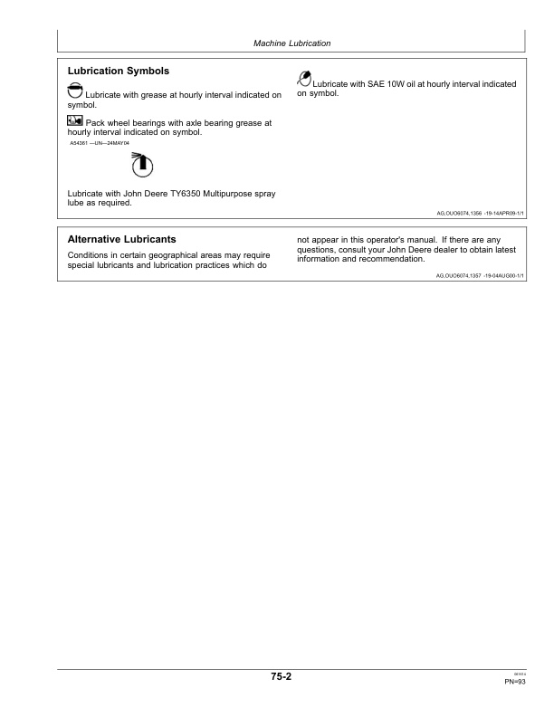
- 1.14.3. Lubrication Symbols
- 1.14.4. Alternative Lubricants
- 1.14.5. Lubrication Intervals
- 1.15. Service and Adjustments
- 1.15.1. Service Intervals
- 1.15.2. Detailed Service InformationUse TM1721
- 1.15.3. Using Safe Service Procedures
- 1.15.4. Practice Safe Maintenance
- 1.15.5. Service and Operate Chemical Sprayers Safely
- 1.15.6. Service Tires Safely
- 1.15.7. Welding Near Electronic Control Units
- 1.15.8. Keep Electronic Control Unit Connectors Clean
- 1.15.9. Tightening Wheel Bolts
- 1.15.10. Checking Tire Inflation
- 1.15.11. Support Machine Before Service
- 1.15.12. Tighten Drive Chains
- 1.15.13. Replace Meter Unit Shear Pin
- 1.15.14. Install and Remove Standard Flush Face Seed Tubes
- 1.15.15. Clean Seed Tube Sensor
- 1.15.16. Adjust Meter Pro Shaft Drive
- 1.15.17. Inspect and Adjust Seed Opener Blades
- 1.15.18. Replace Seed Opener Blades and Seed Tube Guard
- 1.15.19. Adjust Gauge Wheels
- 1.15.20. Center Closing Wheels
- 1.15.21. Adjust Closing Wheel Spacing
- 1.15.22. Replace Cotter Shear Pins
- 1.15.23. Service Wheel Bearings
- 1.15.24. Disk Closing Attachment
- 1.15.25. Inspect and Service Vacuum Meter
- 1.15.26. Inspect and Clean Vacuum Impeller and Housing
- 1.15.27. Clean or Replace Electric AirCompressor Filter
- 1.15.28. Clean Vacuum System
- 1.16. Troubleshooting
- 1.16.1. Row Units
- 1.16.2. Vacuum Meter
- 1.17. Storage
- 1.17.1. Removing From Storage
- 1.17.2. Storing Machine
- 1.17.3. Pneumatic Down Force Storage Procedures
- 1.18. Specifications
- 1.18.1. Unified Inch Bolt and Screw Torque Values
- 1.18.2. Metric Bolt and Screw Torque Values
- 1.18.3. Specifications
- 1.18.4. Record Serial Number
- 1.18.5. Keep Proof of Ownership
- 1.18.6. Keep Machines Secure
- 1.19. John Deere Service Literature
- 1.19.1. Technical Information
- 1.20. John Deere Service Keeps You on the Job
- 1.20.1. John Deere Is At Your Service
- 2. Page Number
- 2.1. Section 05
- 2.2. Section 10
- 2.3. Section 15
- 2.4. Section 20
- 2.5. Section 25
- 2.6. Section 30
- 2.7. Section 35
- 2.8. Section 40
- 2.9. Section 45
- 2.10. Section 50
- 2.11. Section 55
- 2.12. Section 60
- 2.13. Section 65
- 2.14. Section 70
- 2.15. Section 75
- 2.16. Section 80
- 2.17. Section 85
- 2.18. Section 90
- 2.19. Section 95