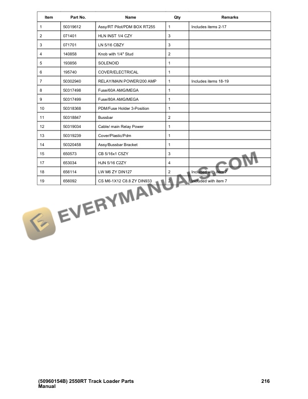
Description
-
Model List:
- 2550RT Compact Track Loader
- 1. SERVICE PARTS AND FILTERS
- 1.1. Filters and Belts
- 1.2. Specialty Tools
- 1.3. Fuid Analysis Kits
- 1.4. Paint
- 2. DECALS
- 2.1. Mustang by Manitou
- 2.2. Common Components
- 2.3. No Heater or A/C
- 2.4. HVAC Rear Bill
- 2.5. Doors
- 2.5.1. FoldUp (Frame)
- 2.5.2. FoldUp Door
- 2.5.3. FoldUp (Top)
- 2.5.4. FoldUp (Bottom)
- 2.5.5. Impact
- 2.5.6. Impact (Components)
- 2.5.7. SwingOut
- 2.5.8. SwingOut (Components)
- 2.6. Windows
- 2.6.1. Side
- 2.6.2. Side (Components)
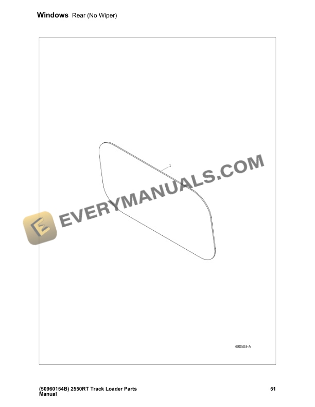
- 2.6.3. Rear (No Wiper)
- 2.6.4. Rear (With Wiper)
- 2.6.5. Washer Bottle (Single Pump)
- 2.6.6. Washer Bottle (Double Pump)
- 2.7. Interior
- 2.7.1. Components (Standard)
- 2.7.2. Headliner (FoldUp Door w/o HVAC)
- 2.7.3. Headliner (FoldUp Door w/ HVAC)
- 2.7.4. HVACDucting
- 2.7.5. HVAC w/ SwingOut Door
- 2.7.6. HVAC w/FoldUp Door
- 2.7.7. Foot Pod and Throttle Control
- 2.7.8. Seat Group
- 2.7.9. Seat (Mechanical)
- 2.7.10. Seat (Air Suspension)
- 2.7.11. Radio Group (Option)
- 2.7.12. Mirrors (Domestic and ROW only)
- 2.8. HVAC
- 2.8.1. Heater Circuit
- 2.8.2. A/C Evaporator
- 2.8.3. A/C Compressor Group
- 2.8.4. A/C Condenser Group
- 3. CONTROLS
- 3.1. Right Control Group
- 3.2. Left Control Group
- 4. CHASSIS
- 4.1. Chassis Components
- 4.2. Chassis Doors
- 4.3. Rear Door and Engine Cover
- 4.4. Counterweight
- 4.5. Counterweight (Option)
- 5. LIFT ARM
- 5.1. Lift Arm
- 5.2. Cover (Standard Hydraulics)
- 5.3. Lift Arm Mirrors
- 5.4. Mirrors (Early Series)
- 5.5. Attachment Bracket (Standard)
- 5.6. Attachment Bracket (Power Attach)
- 6. ENGINE
- 6.1. External Components
- 6.2. Flywheel Housing and Drive Plate
- 6.3. Fuel Circuit
- 6.4. Fuel Tank
- 6.5. Air Intake Group
- 6.6. Exhaust Group
- 6.7. Radiator/Cooler Group
- 7. HYDRAULICS
- 7.1. Hydraulic Tank and Filter Circuit
- 7.2. Drive Pump Fittings
- 7.3. Power Beyond/Track Tension Manifold Fittings
- 7.4. Hydraulic Float Circuit
- 7.5. Standard Hydraulics
- 7.5.1. Pilot Circuit (Standard)
- 7.5.2. Pump Circuit (Standard)
- 7.5.3. Pilot Auxiliary Tubes (Standard)
- 7.5.4. Pilot Level Tubes (Standard)
- 7.5.5. Tilt Hoses (Standard)
- 7.5.6. Lift/Tilt Control Circuit (Standard)
- 7.6. HighFlow Hydraulics
- 7.6.1. Pilot Circuit (HighFlow)
- 7.6.2. Pump Circuit (HighFlow)
- 7.6.3. Pilot Auxiliary Tubes (HighFlow)
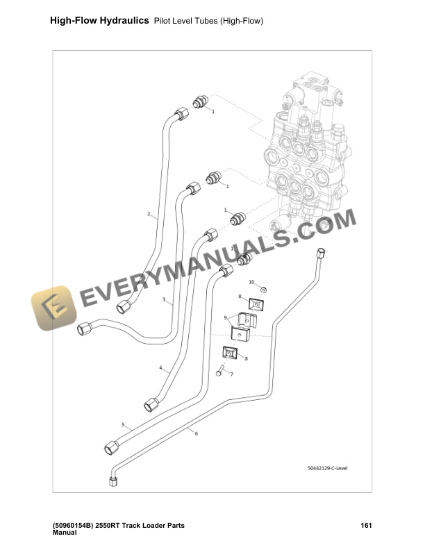
- 7.6.4. Pilot Level Tubes (HighFlow)
- 7.6.5. Pilot Tilt Hoses (HighFlow)
- 7.6.6. Lift/Tilt Control Circuit (HighFlow)
- 7.7. Lift Arm Hydraulics
- 7.7.1. Lift Arm Cylinder Group
- 7.7.2. Lift Arm Hoses (Standard Auxiliary)
- 7.7.3. Lift Arm Hoses (HighFlow)
- 7.8. Components
- 7.8.1. Tandem Pump (Part 1 of 2)
- 7.8.2. Tandem Pump (Part 2 of 2)
- 7.8.3. Spool Pilot Control Valve (PN 50322220)
- 7.8.4. Spool Pilot Control Valve (PN 50322221)
- 7.8.5. Gear Pump (Standard)
- 7.8.6. Gear Pump (HighFlow)
- 7.8.7. Track Tension Manifold
- 7.8.8. Joystick Lift Control (PN 190270)
- 7.8.9. Joystck Drive Control
- 7.8.10. Self Level Valve (Fittings)
- 7.8.11. SelfLevel Valve (PN 135367)
- 7.8.12. SelfLeveling Valve w/ Bypass (PN 271958)
- 7.8.13. Hydraulic Float Manifold (Standard)
- 7.8.14. Hydraglide Manifold (PN 184363)
- 7.9. Cylinders
- 7.9.1. Tilt Cylinder
- 7.9.2. Lift Cylinder
- 7.9.3. Track Tension Cylinder (PN 271414)
- 8. ELECTRICAL
- 8.1. Battery Group
- 8.2. Engine Harness
- 8.3. Chassis Harness
- 8.4. FusesChassis Harness
- 8.5. Power Distribution Module (PDM)
- 8.6. ROPS Harness and Work Lights
- 8.7. Seat Harness
- 8.8. Rear Door Electrical
- 8.9. Backup Camera
- 8.10. Easy Manager
- 8.11. Pin Auxiliary Harness
- 8.12. Fuses14Pin Harness
- 8.13. Power Attachment Harness
- 9. DRIVETRAIN
- 9.1. Drive Motor Circuit (Right Side)
- 9.2. Drive Motor Circuit (Left Side)
- 9.3. Drive Control
- 9.4. Joystick Lockout Circuit
- 9.5. Drive Pump Hoses
- 9.6. Track Tension Circuit
- 9.7. Tracks
- 9.8. Track Drive Components
- 9.8.1. Track Drive Components
- 9.8.2. DualFlange Idler
- 9.8.3. TripleFlange Idler
- 9.8.4. Front Idler
- 9.8.5. Drive Motor Components
- 10. Appendix APages Index
- 11. Appendix BParts Index