Description
-
Model List:
- 3200VT Vertical Lift Track Loader
- 1. Delivery Checklists
- 2. Table of Contents
- 2.1. Contents and Use of this Manual
- 2.2. Safety Symbol and Signal Words
- 2.3. Machine Orientation
- 2.4. Proper Machine Use
- 2.5. Service and Registration
- 2.6. ROPS/FOPS Certification Label
- 2.7. Component Identification
- 2.8. Standard Attachments
- 2.9. Using Attachments
- 2.10. Vibration Information
- 2.11. Fire Extinguisher
- 2.12. Manufacturer Information
- 2.13. Indicator and Operation Symbols
- 3. Safety
- 3.1. Safety Symbol and Signal Words
- 3.2. Mandatory Safety Shutdown Procedure
- 3.3. Before Starting
- 3.4. During Operation
- 3.5. Applications with LoadHandling Devices
- 3.6. Parking the Machine
- 3.7. Electrical Energy
- 3.8. Maintenance and Service Safety Practices
- 3.9. Battery Hazards
- 3.10. Fire Hazards
- 3.11. Additional Safety Equipment
- 3.12. Crystalline Silica Exposure
- 3.13. Transporting the Machine
- 3.14. Lifting the Machine with a Crane
- 3.15. Loading and Transporting the Machine
- 3.16. Safety Decals
- 3.17. ANSIStyle Safety Decals
- 3.18. ISOStyle Safety Decals
- 4. Specifications
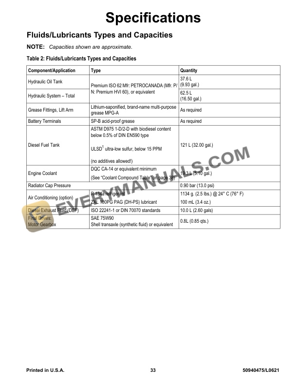
- 4.1. Fluids/Lubricants Types and Capacities
- 4.2. Dimensions
- 4.3. Payloads/Capacities
- 4.4. Weights
- 4.5. Track Drive
- 4.6. Coolant Compound Table
- 4.7. Engine
- 4.8. Hydraulic System
- 4.9. Electrical System
- 4.10. Sound Power/Pressure Levels
- 4.11. Vibration Levels
- 4.12. Features
- 4.13. Standard Features
- 4.14. Optional Features
- 4.15. Common Materials and Densities
- 5. Controls
- 5.1. MultiFunction Display
- 5.2. Control Buttons/Switches
- 5.3. Indicator Panel
- 5.4. Ignition Switch
- 5.5. Seat and Armrest/Joystick Console Adjustment
- 5.6. Control Joysticks
- 5.7. Parking Brake/Work Hydraulics Lockout
- 5.8. Throttle Controls
- 5.9. ECO Mode Switch
- 5.10. Travel Controls
- 5.11. Lift Arm Float Button
- 5.12. Hydraglide Button
- 5.13. HVAC (Option)
- 5.14. Beacon/Work Lights
- 5.15. Wipers/Washers
- 5.16. Battery Disconnect Switch (Option)
- 5.17. Rearview Camera (Option)
- 6. Operation
- 6.1. Operational Checks
- 6.2. Before Operation
- 6.3. Starting the Engine
- 6.4. Warm Up
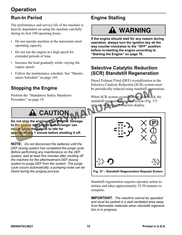
- 6.5. RunIn Period
- 6.6. Stopping the Engine
- 6.7. Engine Stalling
- 6.8. Selective Catalytic Reduction (SCR) Standstill Regeneration
- 6.9. After Operation
- 6.10. JumpStarting
- 6.11. Travel Drive Operation
- 6.12. Rubber Track Use Cautions and Tips
- 6.13. Backup Alarm
- 6.14. Lift Arm Operation
- 6.15. SelfLeveling
- 6.16. Lift Arm Float
- 6.17. Hydraglide Ride Control System
- 6.18. Hydraulics Control Lock
- 6.19. Lift Arm Support
- 6.20. Connecting/Disconnecting Attachments
- 6.21. HydraulicallyPowered Attachments
- 6.22. Pin Connector (Option)
- 6.23. Working with Buckets
- 6.24. Working with Pallet Forks
- 6.25. Lifting the Machine using a Crane
- 6.26. Loading and Transporting the Machine on a Transport Vehicle
- 7. Maintenance
- 7.1. Maintenance Schedule
- 7.2. Engine Maintenance
- 7.3. Diesel Exhaust Fluid (DEF) Service
- 7.4. Fuel System Maintenance
- 7.5. Hydraulic System Maintenance
- 7.6. Hydraulic Hose Maintenance
- 7.7. Travel Motor Maintenance
- 7.8. Track Maintenance
- 7.9. General Lubrication
- 7.10. Tilting ROPS/FOPS
- 7.11. Electrical System
- 7.12. LongTerm Storage
- 7.13. Air Conditioning Maintenance
- 7.14. Window Washer Reservoir
- 7.15. Side Window Removal
- 7.16. Final Shutdown / Decommissioning
- 7.17. Maintenance Log
- 8. Troubleshooting
- 8.1. Engine Troubleshooting
- 8.2. Indicator Troubleshooting
- 8.3. Seal and Hose Troubleshooting
- 8.4. Hydraulic System Troubleshooting
- 8.5. Hydrostatic Travel Drive System Troubleshooting
- 8.6. Electrical Troubleshooting
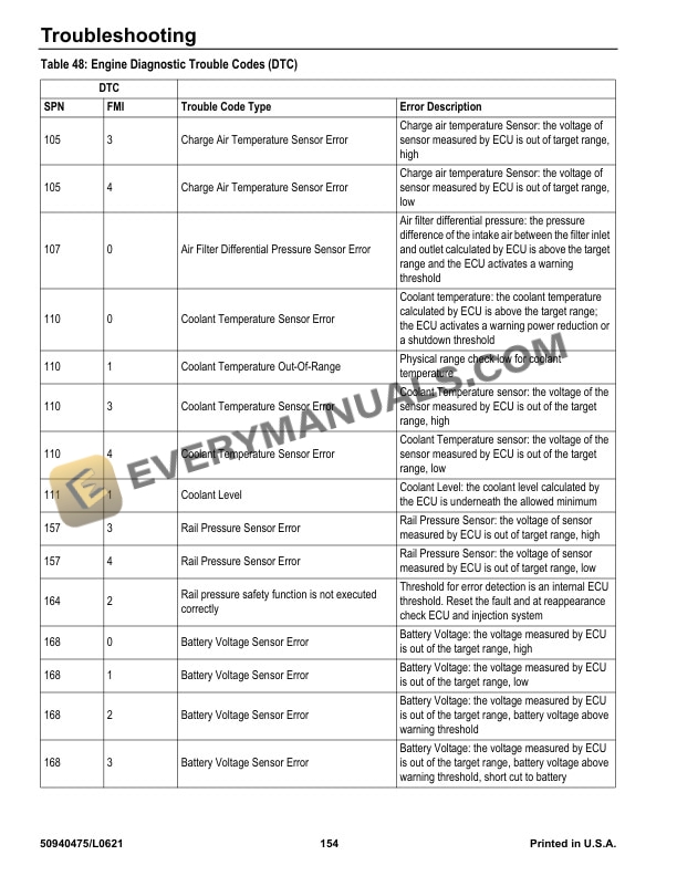
- 8.7. Error Codes
- 9. Schematics
- 9.1. Hydraulic Schematic (Mustang SN 0060301 and Up All Manitou)
- 9.2. Hydraulic Schematic (Mustang SN 0060300 and Before)
- 9.3. Electrical Schematic Chassis (1 of 2) (Mustang SN 0060301 and Up All Manitou)
- 9.4. Electrical Schematic Chassis (2 of 2) (Mustang SN 0060301 and Up All Manitou)
- 9.5. Electrical Schematic Chassis (1 of 2) (Mustang SN 0060300 and Before)
- 9.6. Electrical Schematic Chassis (2 of 2) (Mustang SN 0060300 and Before)
- 9.7. Electrical Schematic Engine (1 of 2) (Mustang SN 0060301 and Up All Manitou)
- 9.8. Electrical Schematic Engine (2 of 2) (Mustang SN 0060301 and Up All Manitou)
- 9.9. Electrical Schematic Engine (1 of 2) (Mustang SN 0060300 and Before)
- 9.10. Electrical Schematic Engine (2 of 2) (Mustang SN 0060300 and Before)
- 9.11. Electrical Schematic Rear Door
- 9.12. Electrical Schematic ROPS/FOPS
- 9.13. Electrical Schematic Seat (1 of 2)
- 9.14. Electrical Schematic Seat (2 of 2)
- 9.15. Electrical Schematic Road Lights
- 9.16. Electrical Schematic 14Pin Connector
- 10. Index
- 11. EC Declaration of Conformity
- 12. Torque Specifications
- 12.1. SAE Torque Values