Description
-
Model List:
- H1 045 Hydrostatic Pump
- H1 053 Hydrostatic Pump
- H1 060 Hydrostatic Pump
- H1 068 Hydrostatic Pump
- 1. Contents
- 2. Introduction
- 2.1. Overview
- 2.2. General instructions
- 2.2.1. Remove the unit
- 2.2.2. Keep it clean
- 2.2.3. Lubricate moving parts
- 2.2.4. Replace all Orings and gaskets
- 2.2.5. Secure the unit
- 2.3. Safety Precautions
- 2.3.1. Unintended machine movement
- 2.3.2. Flammable cleaning solvents
- 2.3.3. Fluid under pressure
- 2.3.3.1. Personal safety
- 2.4. Symbols used in Danfoss literature
- 3. Disassembly
- 3.1. Shaft Seal Removal
- 3.2. Input Shaft
- 3.3. EDC Angle Sensor Removal
- 3.4. Control Removal
- 3.5. Control Disassembly
- 3.6. Remove the Automotive Control
- 3.7. Auxiliary Pad or End Cover Removal
- 3.8. Charge Pump Removal
- 3.9. Pressure Limiter Removal
- 3.10. Charge Pressure Relief Valve Removal
- 3.11. High Pressure Relief Valve Removal
- 3.12. Endcap Removal
- 3.13. Cylinder Block Kit Removal
- 3.14. Servo Sleeve Removal
- 3.15. Servo Piston Removal
- 3.16. Swashplate and Swashplate Bearing Removal
- 3.17. Servo Piston Disassembly
- 3.18. Cylinder Kit
- 3.18.1. Disassemble the cylinder block kit
- 3.18.2. Block spring removal
- 4. Inspection
- 4.1. Overview
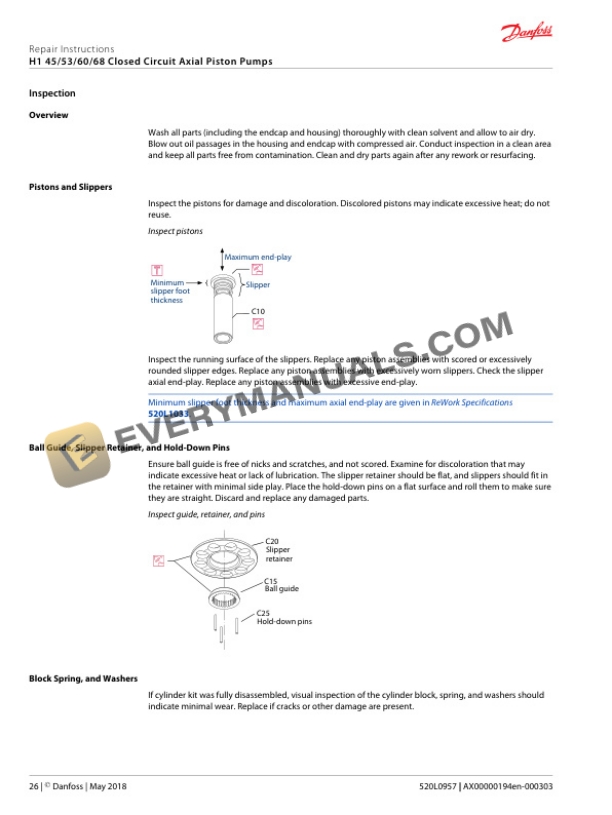
- 4.2. Pistons and Slippers
- 4.3. Ball Guide, Slipper Retainer, and HoldDown Pins
- 4.4. Block Spring, and Washers
- 4.5. Pressure Limiter
- 4.6. HPRV Valve
- 4.7. Cradle Bearings
- 4.8. Optional Displacement Limiter
- 4.9. Charge Pressure Relief Valve
- 4.10. Servo Piston Assembly
- 4.11. Control
- 5. Assembly
- 5.1. Overview
- 5.2. Shaft and Seal Installation
- 5.3. Cradle Bearings and Swashplate Installation
- 5.4. Servo Piston Assembly
- 5.5. Servo Piston Installation
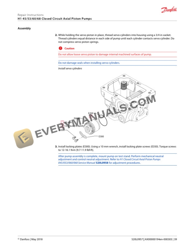
- 5.6. Servo Cylinder Installation
- 5.7. Cylinder Kit Assembly
- 5.8. Cylinder Kit Installation
- 5.9. Timing Pin and Endcap Bushing Installation
- 5.10. Endcap Bushing Installation tools
- 5.11. Endcap Bushing Orientation
- 5.12. Valve Plate and Endcap Installation
- 5.13. Charge Pump Installation
- 5.14. Auxiliary Pad or End Cover Installation
- 5.15. Charge Pressure Relief Valve Installation
- 5.16. Pressure Limiter Installation
- 5.17. HPRV Valve Installation
- 5.18. Optional Displacement Limiter Installation
- 5.19. EDC Angle Sensor Assembly
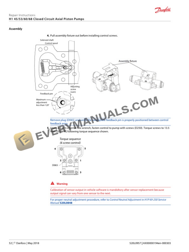
- 5.20. EDC Control with Angle Sensor Installation
- 5.21. Control Assembly
- 5.22. Control Installation
- 5.23. MDC Control
- 5.24. Automotive Control Installation
- 6. Startup procedures
- 6.1. Overview
- 6.2. Initial Startup Procedures
- 6.3. Adjustments
- 6.4. Pressure Measurements
- 7. Port locations
- 7.1. Port Locations and Gauge Installation
- 8. Torque chart
- 8.1. Fastener Size and Torque Chart
- 8.2. Plug Size and Torque Chart
- 8.3. Fasteners and Plugs