Description
-
Model List:
- MC-X 18-2 D K ST3A S1
- MC-X 18-4 D K ST3A S1
- MC-X 25-2 D K ST3A S1
- MC-X 25-4 D K ST3A S1
- MC-X 30-2 D K ST3A S1
- MC-X 30-4 D K ST3A S1
- MSI-X 25 D K ST3A S1
- MSI-X 30 D K ST3A S1
- MSI-X 35 D K ST3A S1
- 1. Page de garde / Front page
- 2. Sommaire général General table of content
- 4. GENERAL, CHARACTERISTICS AND SAFETY
- 4.1. GENERAL INSTRUCTIONS AND SAFETY NOTICE
- 4.1.1. INTRODUCTION
- 4.1.2. SERVICING POSITION
- 4.1.3. EXPLANATION OF SYMBOLS
- 4.1.4. SERVICING RULES
- 4.2. GENERAL CHARACTERISTICS AND SPECIFICATIONS
- 4.2.1. CHARACTERISTICS (MCX)
- 4.2.2. CHARACTERISTICS (MsiX)
- 4.2.3. LUBRICANTS AND FUEL
- 4.2.4. DIMENSIONS (MCX 182 / MCX 184)
- 4.2.5. DIMENSIONS (MCX 252 _ MCX 302/ MCX 254 _ MCX 304)
- 4.2.6. DIMENSIONS (MsiX 20 MSIX 25 MSIX 30)
- 4.3. GENERAL LOCATION
- 4.3.1. LOCATION OF NAME AND IDENTIFICATION PLATE
- 4.4. GENERAL CONTROL AND ADJUSTMENT
- 4.4.1. STANDARD TIGHTENING TORQUES
- 4.4.2. METRIC IMPERIAL UNIT CONVERSION
- 6. ENGINE SPECIFICATION
- 6.1. ENGINE CHARACTERISTICS AND SPECIFICATIONS
- 6.1.1. SPECIFICATIONS
- 6.2. ENGINE location
- 6.2.1. ENGINE COMPONENTS
- 6.2.2. WATER COOLING SYSTEM
- 6.2.3. FUEL SYSTEM
- 6.3. ENGINE CONTROLS AND ADJUSTMENTS
- 6.3.1. Engine SUSPENSION
- 6.3.2. EXHAUST SYSTEM
- 6.3.3. Cooling circuit
- 6.3.4. Adjusting belt tension
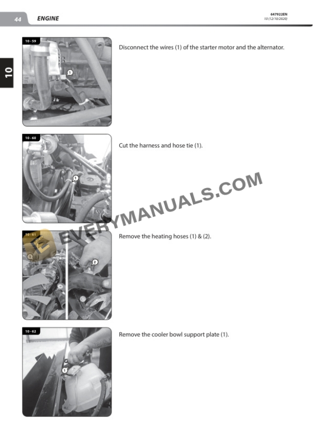
- 6.4. kW ENGINE REMOVAL REFITTING (MCX 18)
- 6.4.1. Removing the alternator
- 6.4.2. Removing the coolant radiator
- 6.4.3. Remove the starter
- 6.4.4. Removing the radiator
- 6.4.5. Removing the engine
- 6.4.6. Removing the fuel tank
- 6.5. kW ENGINE REMOVAL REFITTING (MSIX / MCX 2530)
- 6.5.1. Air filter removal
- 6.5.2. Exhaust pipe removal
- 6.5.3. Radiator removal
- 6.5.4. Alternator removal
- 6.5.5. Starter motor removal
- 6.5.6. Hydrostatic transmission engine removal
- 6.6. ENGINE SPECIFIC TOOLING
- 6.6.1. SPECIAL ENGINE TOOLING
- 6.6.2. ELECTRONIC TENSION METER
- 8. TRANSMISSION
- 8.1. Transmission characteristics and specifications
- 8.1.1. HYDROSTATIC PUMP
- 8.1.2. HYDROSTATIC pump A4VG 40 DA1D7/32R
- 8.1.3. HYDROSTATIC pump A4VG 71 DA1D7
- 8.1.4. HYDRAULIC WHEEL MOTOR MS05
- 8.1.5. HYDRAULIC WHEEL MOTOR MSE05
- 8.1.6. Rear HYDRAULIC WHEEL MOTOR MG02 / MGE02
- 8.1.7. WHEEL DRIVE HYDROSTATIC TRANSMISSION BLOCK
- 8.1.8. WHEEL DRIVE HYDROSTATIC TRANSMISSION BLOCK
- 8.2. HYDROSTATIC TRANSMISSION SCHEMATIC DIAGRAM
- 8.2.1. FORWARD OPERATION fluid direction MCX 18 25 30 in 4 wheel drive
- 8.2.2. FORWARD OPERATION fluid direction MsiX 253035
- 8.2.3. FORWARD OPERATION fluid direction (with valve VPIN/ACC) MCX 18 25 30 in 4 wheel drive
- 8.2.4. FORWARD OPERATION fluid direction (with valve VPIN/ACC) MsiX 253035
- 8.3. Transmission components location
- 8.3.1. Hydrostatic circuit MCX182
- 8.3.2. Hydrostatic circuit MCX184
- 8.3.3. Hydrostatic circuit MCX 25/302
- 8.3.4. Hydrostatic circuit MCX 25/304
- 8.3.5. Hydrostatic circuit MSIX
- 8.4. Transmission controls and adjustments
- 8.4.1. Tightening torque
- 8.4.2. PUMP A4VG 56 DA
- 8.4.3. TRANSMISSION CUTOFF
- 8.4.4. DISENGAGEMENT
- 8.5. TRANSMISSION REMOVAL
- 8.5.1. Removing the front wheel motor
- 8.5.2. Removing the rear wheel motor
- 8.5.3. Remove the hydrostatic pump
- 8.6. Specific transmission tooling
- 8.6.1. HYDROMATIK KIT (Replacement A4VGDA pump / A6VM motor)
- 8.6.2. TH7 VALVE HOSE AND CONNECTOR
- 8.6.3. BASIC MANOMETER BOX
- 8.6.4. DIGITAL MANOMETER BOX
- 10. AXLE
- 10.1. Axle control and adjustment
- 10.1.1. Tightening torque
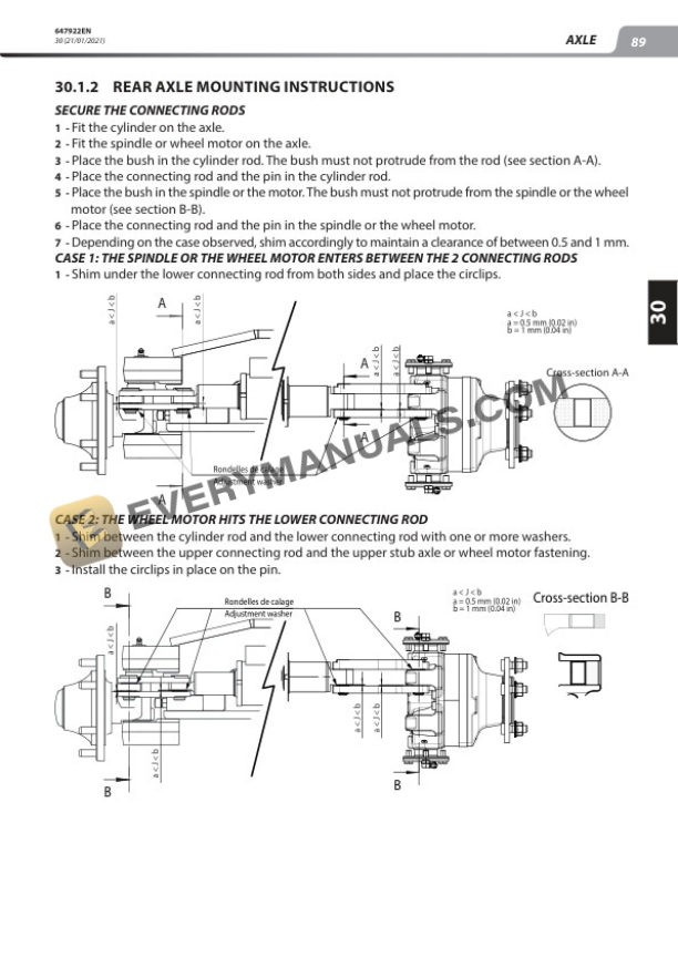
- 10.1.2. Rear axle mounting instructions
- 10.1.3. Post installation inspection
- 10.1.4. Rear axle stop adjustment, 4 wheel drive
- 10.2. Axle removal
- 10.2.1. Removing the rear axle
- 12. BRAKE
- 12.1. Brake characteristics and specifications
- 12.2. Brake diagrams
- 12.3. Brake control and adjustment
- 12.3.1. Inchingbrake pedal adjustment
- 12.3.2. Adjusting the brake contactor
- 14. MAST
- 14.1. CHARACTERISTICS AND SPECIFICATIONS
- 14.1.1. SPECIFICATIONS OF STANDARD MASTS
- 14.2. LOCATION
- 14.2.1. OVERVIEW OF THE MAST ASSEMBLY DVT 3 T
- 14.2.2. OVERVIEW OF THE MAST ASSEMBLY TLL 3 T
- 14.2.3. OVERVIEW OF THE MAST ASSEMBLY TSLL 3 T
- 14.3. CONTROL AND ADJUSTMENT
- 14.3.1. ADJUSTING THE MASTS LIFTING ROLLERS
- 14.3.2. ASSEMBLING THE MAST CHAINS
- 14.3.3. MAST CHAIN TIGHTENING TORQUES
- 14.3.4. CLEARANCE ADJUSTMENT FOR THE LIFTING CYLINDER ASSEMBLY
- 14.4. REMOVAL
- 14.4.1. REMOVING THE FREE LIFT CYLINDER
- 14.4.2. TILTING THE MAST DOWN TO THE GROUND
- 14.4.3. REMOVING THE FREE LIFT MAST
- 14.4.4. REMOVING THE LATERAL LIFTING CYLINDER
- 14.4.5. REMOVING THE INNER MAST UPRIGHT
- 16. HYDRAULICS
- 16.1. Hydraulic characteristics and specifications
- 16.1.1. SDM100 hydraulic valve block
- 16.1.2. SDM100 hydraulic valve block with JSM
- 16.1.3. kW HYDRAULIC PUMP (MCX18)
- 16.1.4. kW HYDRAULIC PUMP (MCX 2530)
- 16.1.5. DOUBLE HYDRAULIC PUMP (MSIX)
- 16.2. Hydraulic diagrams
- 16.2.2. Diagrams
- 16.3. Hydraulic components location
- 16.3.1. MCX 18/25/3024 D K ST3A S1
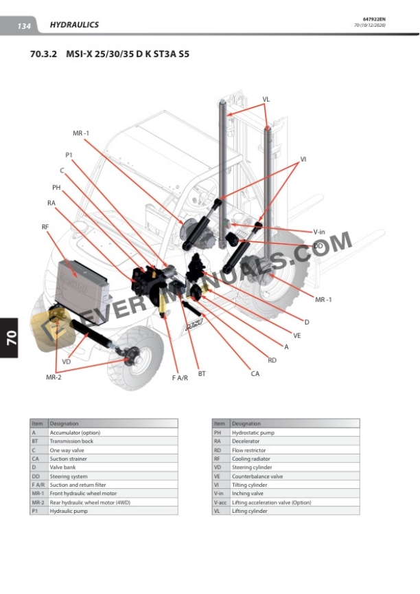
- 16.3.2. MSIX 25/30/35 D K ST3A S5
- 16.4. HYDRAULIC component removal
- 16.4.1. Removing the hydraulic pump
- 16.4.2. Removing the hydraulic tank
- 16.4.3. Replacing the hydraulic pump seals
- 18. ELECTRICITY
- 18.1. Electricity characteristics and specifications
- 18.1.1. BF1 FUSES AND RELAYS
- 18.1.2. Electrical data sheets
- 18.1.3. Electrical component inputs and outputs
- 18.2. Wiring diagrams
- 18.2.1. ELECTRICAL DIAGRAM CODIFICATION EXAMPLE
- 18.2.2. CABLE IDENTIFICATION ON AN ELECTRICAL WIRING HARNESS
- 18.2.3. Installation with JSM
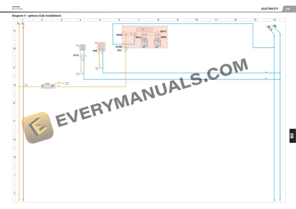
- 18.2.4. Cab installation
- 18.2.5. Drivers cab installation
- 18.3. Electrical location
- 18.3.1. Main harnesses Installation with JSM
- 18.3.2. Main harnesses Cab installation
- 18.3.3. Main harnesses Drivers cab installation
- 18.4. Electrical component removal
- 18.4.1. ECU removal
- 20. DRIVERS CAB
- 20.1. DRIVERS CAB CONTROL AND ADJUSTMENT
- 20.1.1. Installing CAB suspensions
- 20.1.2. Seat fasteners
- 20.2. DRIVERS CAB removal (MCX 18)
- 20.2.1. Raise the cab
- 20.2.2. Raise the cab fully
- 20.3. DRIVERS CAB removal (MSIX)
- 20.3.1. Raising the cab
- 20.3.2. heating block removal
- 20.4. Specific drivers cab tooling
- 20.4.1. Safety strut
- 22. CHASSIS BODYWORK
- 22.1. Characteristics and specifications
- 22.1.1. Tightening torque
- 22.2. REMOVAL REFITTING CHASSIS BODYWORK
- 22.2.1. Removing the counterweight (MCX 18)
- 22.2.2. Removing the counterweight (MSIX)