Description
-
Model List:
- ME 315 48V S3
- ME 316 48V S3
- ME 318 48V S3
- ME 320 48V S3
- ME 315 48V S3 US
- ME 316 48V S3 US
- ME 318 48V S3 US
- ME 320 48V S3 US
- 1. Page de garde / Front page
- 2. Sommaire général General table of content
- 4. GENERAL, CHARACTERISTICS AND SAFETY
- 4.1. Work during the Warranty Period
- 4.2. GENERAL INSTRUCTIONS AND SAFETY NOTICE
- 4.2.1. FOREWORD
- 4.2.2. SERVICING POSITION
- 4.2.3. EXPLANATION OF SYMBOLS
- 4.2.4. SERVICING RULES
- 4.3. GENERAL CHARACTERISTICS AND SPECIFICATIONS
- 4.3.1. CHARACTERISTICS ME 315 316 318 320 48V S3 US
- 4.3.2. LUBRICANTS AND FUEL
- 4.3.3. DIMENSIONS
- 4.4. GENERAL LOCATION
- 4.4.1. LOCATION OF NAME AND IDENTIFICATION PLATE
- 4.5. GENERAL CONTROL AND ADJUSTMENT
- 4.5.1. STANDARD TIGHTENING TORQUES
- 4.5.2. METRIC IMPERIAL UNIT CONVERSION
- 6. TRANSMISSION
- 6.1. Removal of components
- 6.1.1. Front axle transmission electric motor removal
- 8. AXLE
- 8.1. Characteristics and specifications
- 8.1.1. Front reduction gearbox
- 8.1.1.1. Characteristics
- 8.2. Location of components
- 8.2.1. Rear steering axle
- 8.3. Component control and adjustment
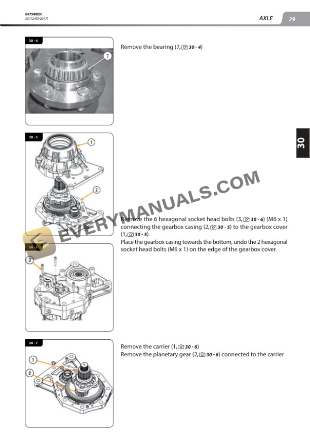
- 8.3.1. Reduction gearbox removal
- 8.3.2. Reduction gearbox installation
- 8.3.3. Steering cylinder removal
- 8.4. Removal of components
- 8.4.1. Steering turret removal
- 10. BRAKE
- 10.1. Flow diagrams and schematic diagrams
- 10.1.1. Brake pedal
- 10.1.2. Brake master cylinder
- 10.2. Component control and adjustment
- 10.2.1. Brake pedal adjustment procedure
- 10.2.2. Brake connection position
- 10.2.3. Parking brake cable adjustment
- 12. MAST
- 12.1. Characteristics and specifications
- 12.1.1. Height of masts
- 12.1.2. Tilt angle of masts
- 12.1.3. Assembly clearance value
- 12.1.4. Tightening torque
- 12.2. Flow diagrams and schematic diagrams
- 12.2.1. Double mast with allround vision
- 12.2.2. Double mast with freeacting lift
- 12.2.3. Triple mast with freeacting lift
- 12.2.4. Lifting cylinder
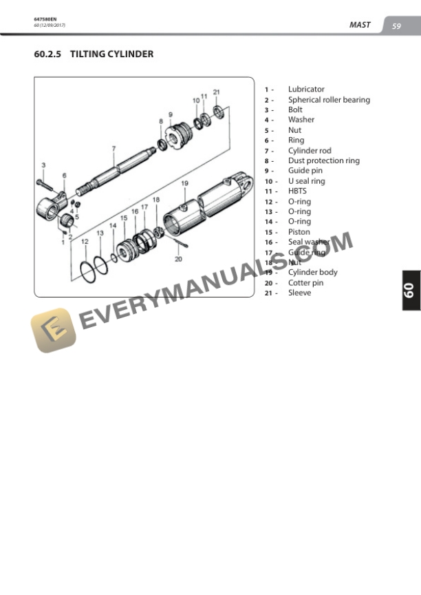
- 12.2.5. Tilting cylinder
- 12.3. Control and adjustment
- 12.3.1. Lifting cylinder removal
- 12.3.2. Bearing roller removal.
- 12.3.3. Inner mast removal
- 12.3.4. Adjustment of rollers and bearings
- 12.3.5. ASSEMBLY OF LH AND RH LIFTING CYLINDERS WITH TEMPORARY ADJUSTMENT.
- 12.3.6. LIFTING CHAIN ADJUSTMENT
- 12.3.7. FORK CARRIAGE CLEARANCE ADJUSTMENT
- 12.4. Mast removal.
- 14. HYDRAULICS
- 14.1. Hydraulic characteristics and specifications
- 14.1.1. Gear pumps
- 14.1.2. Steering pump
- 14.1.3. Distributor
- 14.2. Hydraulic Schematic Diagram
- 14.2.1. Hydraulic diagram key
- 14.2.2. Hydraulic diagram with standard levers
- 14.2.3. Hydraulic diagram with optional mini levers
- 14.3. Location of components
- 14.3.1. Hydraulic system
- 14.3.2. Steering column
- 14.4. Removal of components
- 14.4.1. Hydraulic distributor removal
- 16. ELECTRICITY
- 16.1. Electrical diagram
- 16.1.1. CODES ON THE ELECTRICAL DIAGRAMS
- 16.1.2. Key to diagram ME 315 316 318 320 48V S3 US
- 16.1.3. Standard wiring diagram ME 315 316 318 320 48V S3 US
- 16.1.4. Mini levers option wiring diagram ME 316 318 320 48V S3 US
- 16.2. Control and adjustments
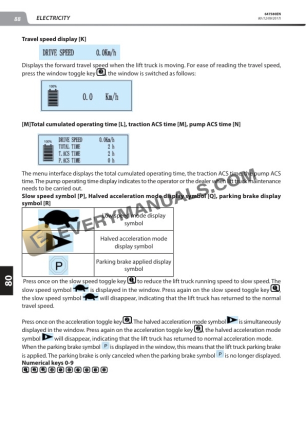
- 16.2.1. Dashboard adjustment procedure
- 16.2.1.1. Lift truck operator parameter viewing procedures
- 16.2.1.2. Dealer parameter viewing procedures
- 16.2.1.3. Password configuration procedure
- 16.2.1.4. Dealer language selection procedures
- 16.2.1.5. Dealer parameter modification procedures
- 16.2.2. Dashboard Adjustment Procedure Summary
- 16.2.2.1. Dealer parameter viewing procedures
- 16.2.3. Steering potentiometer adjustment
- 16.3. Removal of components
- 16.3.1. Dashboard display screen removal
- 16.3.2. Battery removal
- 16.3.3. Hydraulic oil pump electric motor removal
- 16.4. Electrical troubleshooting
- 16.4.1. Error codes
- 18. FRAME BODY
- 18.1. Removal of components
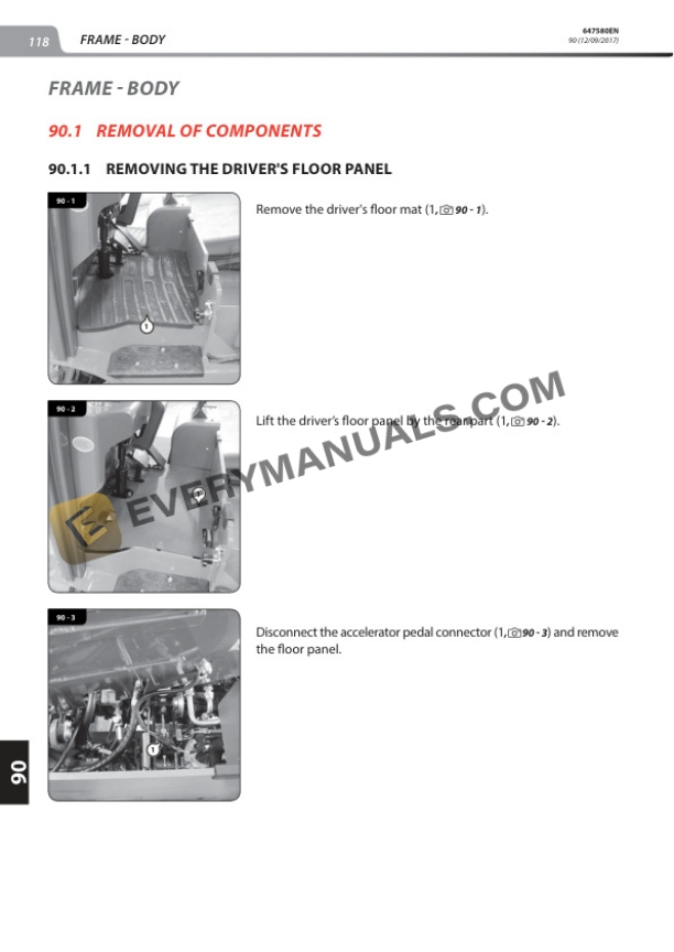
- 18.1.1. Removing the drivers floor panel
- 18.1.2. Counterweight removal
- 20. OPTIONS ATTACHMENTS
- 20.1. Optional mini levers
- 20.1.1. Mini lever characteristics and specifications
- 20.1.1.1. Safety notice
- 20.1.1.2. Name plate
- 20.1.2. location
- 20.1.2.1. Components
- 20.1.2.1.1. Ordering attachments with pin assignment
- 20.1.2.1.2. Emergency stop button with pin assignment
- 20.1.2.1.3. Steering switch with pin assignment
- 20.1.2.1.4. Horn switch with pin assignment
- 20.1.2.1.5. MFA Device wiring harness with pin assignment
- 20.1.3. Control and adjustments
- 20.1.3.1. Removal and assembly
- 20.1.3.1.1. Complete MFA Device
- 20.1.3.1.2. MFA Console
- 20.1.3.1.3. MFA lift truck
- 20.1.3.1.4. Front part of the MFA console
- 20.1.3.1.5. Forward/reverse and height adjustment handle
- 20.1.3.1.6. Fingertip Joystick
- 20.1.3.1.7. Blind cover
- 20.1.3.1.8. Bowden forward/reverse adjustment traction wire
- 20.1.3.1.9. Bowden forward/reverse adjustment traction wire
- 20.1.3.1.10. Bowden height adjustment traction wire
- 20.1.3.1.11. Bowden height adjustment traction wire
- 20.1.3.1.12. Emergency stop button
- 20.1.3.1.13. Steering switch
- 20.1.3.1.14. Horn switch
- 20.1.3.1.15. Armrest
- 20.1.3.1.16. Seat adapter
- 20.1.3.1.17. Lower cover
- 20.1.3.1.18. Lower part with MFA Device wiring harness
- 20.1.4. Troubleshooting
- 20.1.4.1. Potential faults
- 20.1.4.2. Fault location
- 20.1.4.2.1. Diagnosis preconditions for each test
- 20.1.4.2.2. Attachment control inspection
- 20.1.4.2.3. Emergency stop button inspection
- 20.1.4.2.4. Steering switch inspection
- 20.1.4.2.5. Horn switch inspection