Description
-
Model List:
- ME 315 C 24V S3
- ME 315 C 24V S3 US
- 1. GENERAL
- 1.1. GENERAL INSTRUCTIONS AND SAFETY NOTICE
- 1.1.1. FOREWORD
- 1.1.2. SERVICING POSITION
- 1.1.3. EXPLANATION OF SYMBOLS
- 1.1.4. SERVICING RULES
- 1.2. GENERAL CHARACTERISTICS AND SPECIFICATIONS
- 1.2.1. GENERAL CHARACTERISTICS
- 1.2.1.1. ME 315 24V S3 / ME 315 24V S3
- 1.2.2. MAST CHARACTERISTICS AND LOAD CHARTS
- 1.3. GENERAL LOCATION
- 1.3.1. LOCATION OF NAME AND IDENTIFICATION PLATE
- 1.4. GENERAL CONTROL AND ADJUSTMENT
- 1.4.1. STANDARD TIGHTENING TORQUES
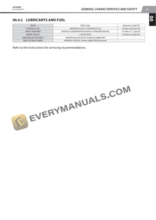
- 1.4.2. LUBRICANTS AND FUEL
- 2. TRANSMISSION
- 2.1. Characteristics and specifications
- 2.1.1. Reduction gearbox
- 2.2. Flow diagrams and schematic diagrams
- 2.3. Location of components
- 2.3.1. Reduction gear box structure
- 2.4. Removal of components
- 2.4.1. Electric traction motor removal
- 3. AXLE
- 3.1. Component diagrams and cross sections
- 3.1.1. Propulsion system
- 3.2. Removal of components
- 3.2.1. Steering turret removal
- 4. BRAKE
- 4.1. Flow diagrams and schematic diagrams
- 4.1.1. Brake pedal
- 4.1.2. Brake master cylinder
- 4.1.3. Brake lining
- 4.2. Component control and adjustment
- 4.2.1. Brake pedal adjustment procedure
- 5. MAST
- 5.1. Characteristics and specifications
- 5.1.1. Dimension and Weight of standard mast
- 5.2. Description
- 5.2.1. Double mast
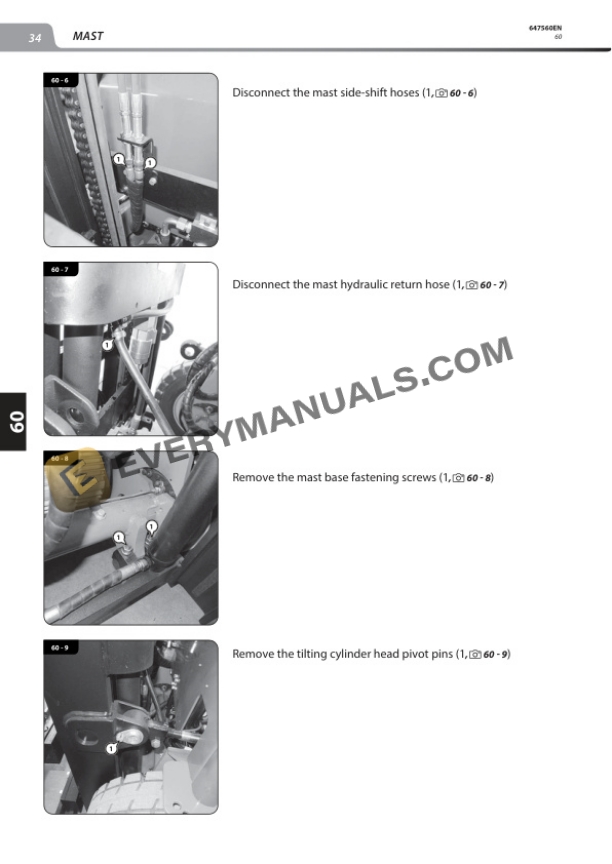
- 5.3. Mast removal
- 6. HYDRAULICS
- 6.1. Hydraulic characteristics and specifications
- 6.1.1. Hydraulic steering motor
- 6.1.2. Hydraulic steering pump
- 6.1.3. Gear pumps
- 6.1.4. Hydraulic valve bank
- 6.1.5. Hydraulic control valve
- 6.2. Schematic diagram
- 6.3. Hydraulic component sections and diagrams
- 6.3.1. Steering column
- 6.4. Removal hydraulic components
- 6.4.1. Control valve removal
- 7. ELECTRICITY
- 7.1. Characteristics and specifications
- 7.1.1. Hydraulic pump electric motor
- 7.1.2. Traction electric motor
- 7.1.3. BATTERY
- 7.2. electrical diagram
- 7.2.1. CODES ON THE ELECTRICAL DIAGRAMS
- 7.2.2. Diagram key
- 7.2.3. Diagram
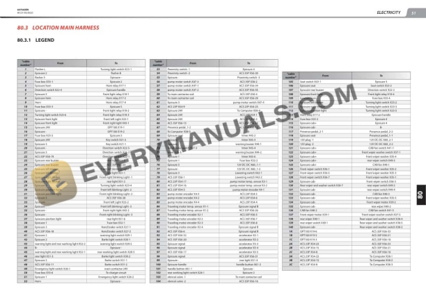
- 7.3. Location Main harness
- 7.3.1. legend
- 7.3.2. Harness
- 7.4. Control and adjustments
- 7.4.1. Dashboard adjustments
- 7.4.1.1. Lift truck operator parameter viewing procedures
- 7.4.1.2. Dealer parameter viewing procedures
- 7.4.1.3. Password configuration procedure
- 7.4.1.4. Dealer language selection procedures
- 7.4.1.5. Dealer parameter modification procedures
- 7.5. Electrical components removal
- 7.5.1. Dashboard display screen removal
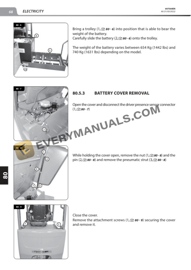
- 7.5.2. Battery removal
- 7.5.3. Battery cover removal
- 7.5.4. Hydraulic oil pump electric motor removal
- 7.6. Troubleshooting
- 8. DRIVERS CAB
- 8.1. Removal
- 8.1.1. Overhead guard removal. (ME315c24v S3 US)
- 9. FRAME BODY
- 9.1. Frame body removal
- 9.1.1. Driver floor panel removal ME 315 C 24V S3 US
- 9.1.2. Counterweight removal