Description
-
Model List:
- MT-X 733 95P ST3A S1
- MT-X 1033 ST 100P ST3A S1
- 1. Page de garde / Front page
- 2. Sommaire général General table of content
- 4. GENERAL, CHARACTERISTICS AND SAFETY
- 4.1. Work during the Warranty Period
- 4.2. GENERAL INSTRUCTIONS AND SAFETY NOTICE
- 4.2.1. FOREWORD
- 4.2.2. SERVICING POSITION
- 4.2.3. EXPLANATION OF SYMBOLS
- 4.2.4. SERVICING RULES
- 4.3. GENERAL CHARACTERISTICS AND SPECIFICATIONS
- 4.3.1. CHARACTERISTICS
- 4.3.2. LUBRICANTS AND FUEL
- 4.3.3. Dimensions
- 4.4. General location
- 4.4.1. Location of the name and identification plate
- 4.5. GENERAL CONTROL AND ADJUSTMENT
- 4.5.1. STANDARD TIGHTENING TORQUES
- 4.5.2. METRIC IMPERIAL UNIT CONVERSION
- 6. ENGINE SPECIFICATION
- 6.1. ENGINE CHARACTERISTICS AND SPECIFICATION
- 6.1.1. ELECTRONIC CONTROL MODULE ECM
- 6.1.2. ENGINE EARTH
- 6.1.3. LOW PRESSURE FUEL CIRCUIT
- 6.1.4. HIGH PRESSURE FUEL CIRCUIT
- 6.2. Engine control and adjustment
- 6.2.1. ENGINE TIGHTENING TORQUES
- 6.2.2. Fuel gauge adjustment procedure
- 6.2.3. ALTERNATOR/CRANKSHAFT BELT ADJUSTMENT
- 6.2.4. COOLING CIRCUIT ADJUSTMENT
- 8. TRANSMISSION
- 8.1. Transmission components location
- 8.1.1. PG 115 GEAR BOX
- 8.2. Transmission control and adjustment
- 8.2.1. Tightening torque
- 8.3. Transmission removal
- 8.3.1. PREPARATION AND SAFETY INSTRUCTIONS
- 8.3.2. REMOVE THE GEARBOX
- 8.4. Specific transmission tooling
- 8.4.1. Basic manometer box
- 8.4.2. Digital Manometer box
- 8.4.3. HYDROMATIK KIT (2nd fitting Pump A 4 VG DA/Engine A 6 VM DA)/hose and valve connector TH7
- 8.4.4. GEARBOX REMOVAL TOOLS
- 10. AXLE
- 10.1. Axle controls and adjustments
- 10.1.1. Tightening torques
- 12. BRAKE
- 12.1. Characteristics and specifications
- 12.1.1. Parking brake
- 12.1.2. Service brake
- 12.2. Locations
- 12.2.1. Hydraulic braking circuits MTX 733 95P ST3A S1 et MTX 1033 100P ST3A S1
- 12.3. Control and adjustment
- 12.3.1. Adjusting the pedal height
- 12.3.2. BLEEDING THE BRAKE CIRCUIT
- 12.3.3. ADJUSTING THE PARKING BRAKE CALLIPER
- 12.3.4. CHECKING AND ADJUSTING THE PARKING BRAKE WITH THE LEVER
- 12.4. Removals
- 12.4.1. REMOVE THE BRAKING ASSISTANCE
- 12.4.2. REMOVE THE MASTER CYLINDER
- 12.4.3. REMOVE THE PARKING BRAKE PADS
- 12.5. Specific tooling
- 12.5.1. Brake fluid bleeder
- 14. BOOM
- 14.1. Boom characteristics and specifications
- 14.1.1. Duplex Boom
- 14.1.2. TRIPLEX BOOM
- 14.2. Location
- 14.2.1. MAIN COMPONENTS OF THE DUPLEX BOOM (6 and 7 m)
- 14.2.2. MAIN COMPOENTS OF THE TRIPLEX BOOM (9 and 10 m)
- 14.3. Control and adjustment
- 14.3.1. TIGHTENING TORQUES/LUBRICATION
- 14.4. Removal refitting
- 14.4.1. Removal of elements
- 14.4.2. Remove the TRIPLEX BOOM
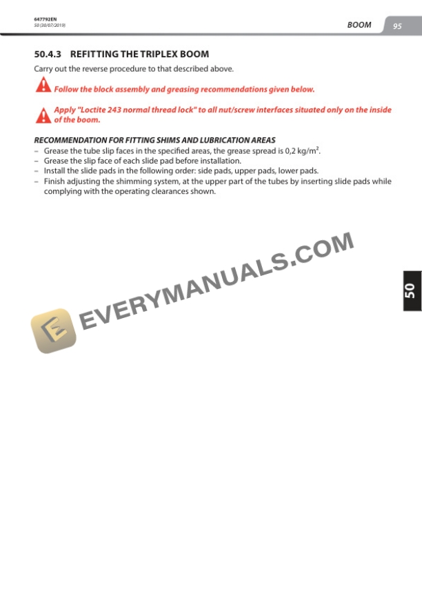
- 14.4.3. Refitting the TRIPLEX BOOM
- 14.4.4. Boom removal
- 16. HYDRAULICS
- 16.1. Hydraulic characteristics and specifications
- 16.1.1. Hydraulic component sheets
- 16.2. Hydraulic schematic diagrams
- 16.2.1. MTX 733 95P ST3A S1
- 16.2.2. MTX 1033 ST 100P ST3A S1
- 16.3. Hydraulic components location
- 16.3.1. MTX 733 95P ST3A S1
- 16.3.2. MTX 1033 ST 100P ST3A S1
- 16.4. Hydraulic controls and adjustments
- 16.4.1. Distributor control logic
- 16.4.2. Aggravating movements cutoff operating principle
- 16.4.3. CASAPPA KP30 22 pump tightening torques
- 16.5. Specific tooling
- 16.5.1. Basic and digital manometer box
- 16.5.2. INFLATION KIT BOX
- 18. ELECTRICITY
- 18.1. Electricity characteristics and specifications
- 18.1.1. Relay and fuse holder electric plate
- 18.1.2. ECU Inputs/Outputs
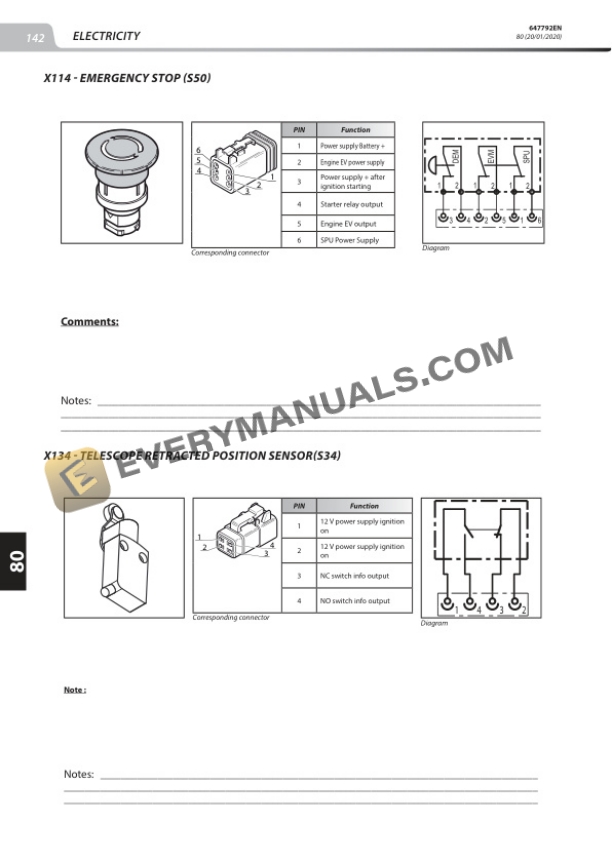
- 18.1.3. Electrical component sheets
- 18.2. Wiring diagrams
- 18.2.1. Examples of coding on the wiring diagrams
- 18.2.2. Cable marking on an electrical wiring harness
- 18.2.3. MTX 733 95P ST3A S1
- 18.2.4. MTX 1033 ST 100P ST3A S1
- 18.3. Electricity locations
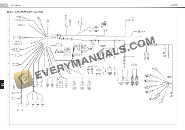
- 18.3.2. Main harness MTX 733 2D
- 18.3.3. Main harness MTX 733 3D
- 18.3.4. Main harness MTX 1033 2D
- 18.3.5. Main harness MTX 1033 3D
- 18.3.6. Engine 2D harness
- 18.3.7. Engine 3D harness
- 18.3.8. Distributor 2D harness
- 18.3.9. Distributor 3D harness
- 18.4. CONTROL AND ADJUSTMENT
- 18.4.1. BOOM ANGLE ANGULAR SENSOR ADJUSTMENT
- 18.4.2. LONGITUDINAL STABILITY INDICATOR (LLMI)
- 18.5. Electricity removal refit
- 18.5.1. Replace the strain gauge
- 18.6. Troubleshooting
- 18.6.1. ERROR CODES
- 18.7. SPECIFIC TOOLING
- 18.7.1. BREAKOUT BOXES
- 18.7.2. Electrovalve adapter
- 18.7.3. DIAGNOSTIC TOOLS
- 20. DRIVERS CAB
- 20.1. Drivers cab control and adjustment
- 20.1.1. Tightening torques
- 22. OPTIONS ATTACHMENTS
- 23. AIR CONDITIONING OPTION
- 23.1. Characteristics and specifications
- 23.1.1. Description of operation
- 23.1.2. Operating principle
- 23.2. Location
- 23.2.1. Location
- 23.3. Air conditioning controls and adjustments
- 23.3.1. General check points
- 23.3.2. ASSEMBLY INSTRUCTIONS FOR AIR CONDITIONING CIRCUIT
- 23.3.3. Safety measures for handling the r134a
- 23.3.4. Refrigerant fluid load for the air conditioning circuit
- 23.3.5. AIRCONDITIONING INSPECTION FORM
- 23.4. Removal refit
- 23.4.1. Air conditioning belt removal
- 23.4.2. Air conditioning belt refit
- 23.5. Air conditioning troubleshooting
- 23.5.1. Temperature troubleshooting
- 23.5.2. ABNORMAL NOISE ON A/C SYSTEM
- 23.5.3. UNPLEASANT SMELL
- 23.6. Specific tooling
- 23.6.1. Fitting wedge for elastic drive belt
- 24. CLEANFIX OPTION
- 24.1. Characteristics
- 24.1.1. Presentation
- 24.2. Schematic diagram
- 24.3. Specific tooling
- 24.3.1. Repair kit
- 24.3.2. Maintenance