Description
-
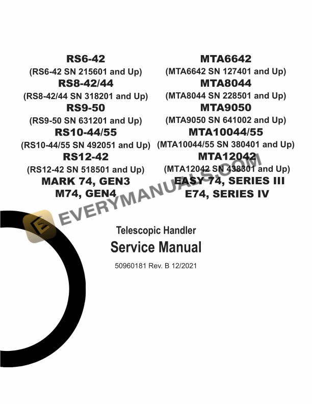
Model List:
- RS6-42
- RS8-42
- RS8-44
- RS9-50
- RS10-44
- RS10-55
- RS12-42
- MARK 74 GEN3
- M74 GEN4
- MTA6642
- MTA8044
- MTA9050
- MTA10044
- MTA10055
- MTA12042
- EASY 74 SERIES III
- E74 SERIES IV
- 1. Introduction
- 1.1. Safety Symbol and Signal Words
- 1.2. Contents and Use of this Manual
- 1.3. Machine Orientation
- 1.4. Proper Machine Use
- 1.5. Service and Registration
- 1.6. Component Identification Left Side
- 1.7. Component Identification Right Side
- 1.8. List of Attachments
- 1.9. Using Attachments
- 1.10. Manufacturer Information
- 1.11. Indicator and Operation Symbols
- 2. Safety
- 2.1. Safety Symbol and Signal Words
- 2.2. Mandatory Safety Shutdown Procedure
- 2.3. Before Operation Safety Reminders
- 2.4. Operation Safety Reminders
- 2.5. Provision for Stability/Avoiding Rollover Accidents
- 2.6. Applications with LoadHandling Devices
- 2.7. Suspended Load Safety Reminders
- 2.8. Parking the Machine
- 2.9. Electrical Energy
- 2.10. Maintenance and Service Safety Practices
- 2.11. Battery Hazards
- 2.12. Fire Hazards
- 2.13. Additional Safety Equipment
- 2.14. Crystalline Silica Exposure
- 2.15. Personnel Work Platform (PWP) System
- 2.16. Wireless Remote Battery Replacement
- 2.17. Work Platform Design Requirements (Per ANSI/ITSDF B56.6 2016, Sec. 8.24)
- 2.18. Safety Decals
- 2.19. New Decal Application
- 3. Lubrication
- 3.1. General Information
- 3.2. Types of Lubricants and Capacities
- 3.3. Lubrication Points
- 3.4. Filter Table
- 4. Maintenance
- 4.1. Maintenance Schedule
- 4.2. Maintenance Interval
- 4.3. Engine Maintenance
- 4.4. Fuel System Maintenance
- 4.5. Diesel Exhaust System (DEF) Maintenance
- 4.6. Transmission Maintenance
- 4.7. Axle Maintenance
- 4.8. Hydraulic System Maintenance
- 4.9. Tire and Wheel Maintenance
- 4.10. Battery and Cable Maintenance
- 4.11. HVAC/Air Conditioning Maintenance
- 4.12. Check Instruments Operation
- 4.13. Check General Machine Operation and Condition
- 4.14. Check Personnel Work Platform (PWP) System (if used)
- 4.15. Storage
- 4.16. PWP System Operational Troubleshooting
- 5. Powertrain
- 5.1. Engine (Cummins)
- 5.2. Engine (Deutz 74hp)
- 5.3. Engine (Deutz 120hp)
- 5.4. TRANSMISSION
- 5.5. REAR AXLE
- 5.6. Front Axle
- 6. Hydraulics
- 6.1. Main Hydraulic Control Valve
- 6.2. Main Gear Pump
- 6.3. Steering Motor
- 6.4. Lift Cylinder
- 6.5. Slave Cylinder
- 6.6. Frame Leveling Cylinder
- 6.7. Tilt Cylinder
- 6.8. Cylinder Repair
- 6.9. Stabilizer Cylinder Removal and Installation
- 6.10. Stabilizer Cylinder Repair
- 6.11. Boom Extend Cylinder Removal and Installation (3Section Boom)
- 6.12. Boom Extend Cylinder Removal and Installation (4Section Boom)
- 6.13. Hydraulic Testing and Adjustment Procedures
- 7. HYDRAULIC Schematics
- 7.1. Hydraulic Schematic without PWP
- 7.2. Hydraulic Schematic with PWP
- 8. Electrical Controls Systems
- 8.1. Electrical Control System General Information
- 8.2. Control Modules
- 8.3. Display, Indicators, and Controls
- 8.4. Fuses, Relays, and Resistors
- 8.5. Engine Diagnostic Trouble Codes (DTCs)
- 9. Electrical Schematics
- 9.1. Cummins Engine Electrical Schematic (1 of 5) Startup / Customer Digicode
- 9.2. Cummins Engine Electrical Schematics (1 of 5) Legends
- 9.3. Cummins Engine Electrical Schematics (2 of 5) CAN / ECU
- 9.4. Cummins Engine Electrical Schematics (2 of 5) Legends
- 9.5. Cummins Engine Electrical Schematics (3 of 5) Switch Operated Functions / Movement
- 9.6. Cummins Engine Electrical Schematics (3 of 5) Legends
- 9.7. Cummins Engine Electrical Schematics (4 of 5) Fan / AirConditioner and Wipers
- 9.8. Cummins Engine Electrical Schematics (4 of 5) Legends
- 9.9. Cummins Engine Electrical Schematics (5 of 5) Lighting
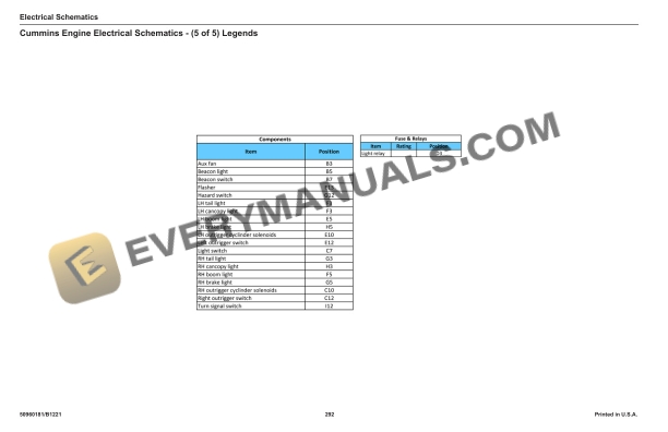
- 9.10. Cummins Engine Electrical Schematics (5 of 5) Legends
- 9.11. Deutz Engine Electrical Schematic (120 hp engine page 1 of 3)
- 9.12. Deutz Engine Electrical Schematic (120 hp engine page 2 of 3)
- 9.13. Deutz Engine Electrical Schematic (120 hp engine page 3 of 3)
- 9.14. Deutz Engine Electrical Schematics (74 hp engine page 1 of 2)
- 9.15. Deutz Engine Electrical Schematics (74 hp engine page 2 of 2)
- 11. TELESCOPIC BOOM
- 11.1. General Information
- 11.2. Boom Assembly
- 11.3. Single and Double Leaf Chain Adjustments (3Section Boom)
- 11.4. Inner Boom Section Removal and Installation (3Section Boom)
- 11.5. Double Chain and Roller Bearing Replacement (3Section Boom)
- 11.6. Single Chain and Roller Bearing Replacement (3Section Boom)
- 11.7. Intermediate Boom Section Removal and Installation (3Section Boom)
- 11.8. Boom Pad Replacement (3Section Boom).
- 11.9. Overview 4Section Boom
- 11.10. Boom Assembly Removal and Installation (4Section Boom)
- 11.11. t Intermediate Boom Section Removal and Installation (4Section Boom)
- 11.12. d Intermediate Boom Section Removal and Installation (4Section Boom)
- 11.13. Inner Boom Section Removal and Installation (4Section Boom)
- 11.14. Boom Hydraulic Hose and Tube Replacement (4Section Boom)
- 11.15. Boom Pad Overview (4Section Boom)
- 11.16. Boom Pad Replacement (4Section Boom)
- 11.17. t Intermediate Boom
- 11.18. d Intermediate Boom Rear Pad Replacement
- 11.19. d Intermediate Boom Front Pad Replacement
- 11.20. Inner Boom
- 11.21. Overview Boom Chain and Rollers (4Section Boom)
- 11.22. Inner Boom Top Chain and Roller Replacement (4Section Boom)
- 11.23. Bottom Inner Boom Chain and Roller Replacement (4Section Boom)
- 11.24. d Intermediate Boom Chain and Roller Replacement (4Section Boom)
- 11.25. Outer Boom Chain and Roller Replacement (4Section Boom)
- 11.26. Boom Chain Adjustment (4Section Boom)
- 12. SPECIFICATION
- 12.1. Machine Configuations
- 12.2. Lifting Performance
- 12.3. General Dimensions
- 12.4. MultiFunctional Display
- 12.5. Visual Indicators
- 12.6. Steering System
- 12.7. Braking System
- 12.8. Electrical System
- 12.9. Service Capacities
- 12.10. Transmission Type
- 12.11. Axles (Front and Rear)
- 12.12. Operators Station