Description
-
Model List:
- AL550 Articulated Loader
- AL508 Articulated Loader
- MLA 5-60 Articulated Loader
- 1. Table of Contents
- 2. General
- 2.1. Manual Purpose/Foreword
- 2.2. Manufacturer Information
- 2.3. Proper Machine Use
- 2.4. Product Support
- 2.5. Additional Service Documentation
- 2.6. Characteristics and Specifications
- 2.7. Direct and/or Indirect Visibility
- 2.8. Reference Information
- 2.9. Indicator and Operation Symbols
- 3. Safety
- 3.1. Safety Symbol and Signal Words
- 3.2. Mandatory Safety Shutdown Procedure
- 3.3. Before Starting
- 3.4. During Operation
- 3.5. Provision for Stability/Avoiding Rollover and Tipover Accidents
- 3.6. Articulated Loader Stability
- 3.7. Applications with LoadHandling Devices
- 3.8. Parking the Machine
- 3.9. Electrical Energy
- 3.10. Maintenance and Service Safety Practices
- 3.11. Battery Hazards
- 3.12. Fire Hazards
- 3.13. Additional Safety Equipment
- 3.14. Crystalline Silica Exposure
- 3.15. Transporting the Machine
- 3.16. Raising the Machine with a Crane
- 3.17. Loading and Transporting the Machine
- 3.18. Safety Decals
- 3.19. Safety Decal Locations
- 3.20. ANSIStyle and Common Safety Decal Locations
- 3.21. ISOStyle Safety Decal Locations
- 4. Machine Service Operation
- 4.1. Additional Information
- 4.2. Mandatory Safety Shutdown Procedure
- 4.3. Preparation and Safety Instruction
- 4.4. Lift Structure Support
- 4.5. Hydraulics Transport LockOut Operation
- 4.6. Auxiliary Circuit Pressure Relief
- 4.7. Raising the Machine using a Crane
- 4.8. Towing
- 4.9. Loading and Transporting the Machine on a Transport Vehicle
- 4.10. LongTerm Storage
- 4.11. Final Shutdown / Decommissioning
- 5. Engine
- 5.1. Engine Specifications
- 5.2. Engine Assembly
- 5.3. Engine Operation
- 5.4. Engine Maintenance
- 5.5. Belt Maintenance / Service
- 5.6. Engine Removal
- 5.7. Engine Installation
- 5.8. Engine Troubleshooting
- 6. Engine Cooling System
- 6.1. Engine Cooling System General Information
- 6.2. Cooling Package Removal
- 6.3. Cooling Package Installation
- 7. Drive System / Transmission
- 7.1. Drive System General Information
- 7.2. Hydrostatic Travel Motor
- 7.3. Pump and Drive Motor Error Codes
- 7.4. Travel Motor Service
- 7.5. Hand/Foot Throttle
- 7.6. Transmission Control Unit (TCU) / Drive Controller
- 8. Axles
- 8.1. Hydrostatic Drive Motor
- 9. Brake
- 9.1. Brake/Inching Pedal Calibration
- 9.2. Bleeding the Brake System
- 9.3. Brake/Inching Pedal Electrical
- 9.4. Parking Brake Adjustment/Service
- 10. Lift Structure
- 10.1. Lift Structure Hydraulics
- 11. Hydraulics
- 11.1. Hydraulic System General Information
- 11.2. General Hydraulic Service Notes
- 11.3. Main Pressure Test and Adjustment
- 11.4. HighFlow Auxiliary Hydraulics Pressure Test and Adjustment
- 11.5. Control Valve
- 11.6. Tilt/Lift Cylinder Tests
- 11.7. Hydraulic Cylinder Disassembly/ Assembly
- 11.8. Hydraulic Solenoid Valves and Tests
- 11.9. Hydraglide
- 11.10. Solenoid Valve Disassembly/ Reassembly
- 11.11. Steering
- 11.12. Hydraulic Gear Pump
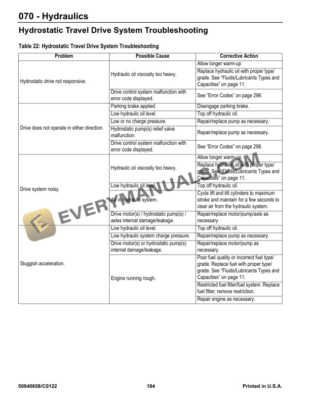
- 11.13. Hydraulic System Troubleshooting
- 11.14. Hydrostatic Travel Drive System
- 12. Hydraulic Schematics
- 12.1. Hydraulics Schematic StandardFlow Auxiliary
- 12.2. Hydraulics Schematic HighFlow Auxiliary
- 12.3. Hydraulics Schematic StandardFlow Auxiliary with Options
- 12.4. Hydraulics Schematic HighFlow Auxiliary with Options
- 13. Electrical System
- 13.1. Battery
- 13.2. Power Distribution
- 13.3. Control Modules
- 13.4. J1939 Data Connector
- 13.5. Easy Manager
- 13.6. Throttle Pedal Electrical/CAN
- 13.7. Hand Throttle Electrical
- 13.8. Brake/Inching Pedal Electrical
- 14. Wire Harness Diagrams
- 14.1. Wire Harness Diagram Front Chassis
- 14.2. Wire Harness Diagram Rear Chassis
- 14.3. Wire Harness Diagram Lower ROPS/FOPS (1 of 2)
- 14.4. Wire Harness Diagram Lower ROPS/FOPS (2 of 2)
- 14.5. Wire Harness Diagram Upper ROPS/FOPS
- 14.6. Wire Harness Diagram Steering Column
- 14.7. Wire Harness Diagram HVAC
- 14.8. Wire Harness Diagram Rear Electrical Auxiliary
- 14.9. Wire Harness Diagram Front Electrical Auxiliary
- 15. Electrical Schematics
- 15.1. Electrical Schematic Rear Chassis
- 15.2. Electrical Schematic Front Chassis
- 15.3. Electrical Schematic Power Distribution
- 15.4. Electrical Schematic Grounds
- 15.5. Electrical Schematic Lower ROPS/FOPS
- 15.6. Electrical Schematic Upper ROPS/FOPS
- 15.7. Electrical Schematic Steering Column
- 15.8. Electrical Schematic HVAC
- 15.9. Electrical Schematic CAN Network
- 15.10. Electrical Schematic Lights
- 15.11. Electrical Schematic Engine (Deutz TD 2.2 L3)
- 15.12. Electrical Schematic Electrical Auxiliary Circuits
- 15.13. Electrical Schematic Hydraulics Electrical
- 16. Operation Station
- 16.1. HVAC System
- 17. Chassis
- 17.1. Chassis General Information
- 17.2. Side Panel Removal/Replacement
- 17.3. Rear Cover Removal/Replacement
- 17.4. Service Cover Removal/Replacement
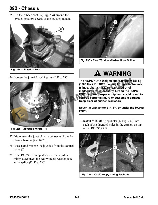
- 17.5. ROPS/FOPS
- 17.6. Engine Cover Removal/Replacement
- 17.7. Articulation Joint
- 18. Electrical Control System
- 18.1. Electrical Control System General Information
- 18.2. Control Modules
- 18.3. CAN System Service/Computer Connection
- 18.4. Operation/Controller Area Network (CAN) Functional Organization
- 18.5. Accessories and Options Electrical Functional Detail
- 18.6. CAN/Control System Troubleshooting
- 19. Index
- 20. Torque Specifications