Description
-
Model List:
- 200 ATJ RC ST5 S1
- 200 ATJ ST5 S1
- 1. Legal disclaimer
- 2. Foreword
- 3. Intervention during the warranty period
- 4. Supplier Documentation List
- 5. Safety
- 5.1. Servicing Rules
- 6. Machine Service Operations
- 6.1. Servicing position
- 6.2. Preparation and safety instructions MEWP
- 7. Characteristics and specifications
- 7.1. Characteristics (200 ATJ ST5)
- 7.2. Dimensions (200 ATJ ST5)
- 7.3. Lubricants and fuel (200 ATJ ST5)
- 8. Reference information
- 8.1. Explanation of symbols
- 8.2. List of Abbreviations
- 8.3. Standard tightening torques
- 8.4. Metric imperial unit conversion
- 9. Location of name and identification plate
- 9.1. Location of name and identification plates
- 10. Characteristics and specifications
- 10.1. General characteristics Yanmar 3TNV88CKMU
- 11. Location
- 11.1. Location of engine components Yanmar 4TNV88CKMU 200 ATJ
- 11.2. Location of cooling system components 200 ATJ ST5
- 11.3. Location of air system components 200 ATJ ST5
- 11.4. Location of fuel system components 200 ATJ ST5
- 12. Control and adjustment
- 12.1. DEF regeneration management
- 12.2. Tightening torques for the shock mounts 200 ATJ ST5
- 13. Removal
- 13.1. Removing the engine cover
- 13.2. Removing the engine 200 ATJ ST5
- 14. Refit
- 14.1. Installing Engine Components
- 15. Characteristics and specifications
- 15.1. Supplier Documentation
- 16. Location
- 16.1. Location of hydrostatic components 200ATJ ST5
- 16.2. Location of hydrostatic pump pressure ports 260TJP/280TJ ST5
- 16.3. Location of hydrostatic pump adjustment ports 260TJP/280TJ ST5
- 17. Control and adjustment
- 17.1. Requirements for hydrostatic adjustmentsA4VG56A10VG45TJ
- 17.2. Adjusting the LP booster valveA4VG56A10VG45TJ
- 17.3. Adjusting the idle point A4VGA10VGTJ
- 17.4. Adjusting the flow cancellation valve A4VGA10VGTJ
- 17.5. Adjusting the HP valves A4VGA10VGTJ
- 18. Removal
- 18.1. Removing the engine cover
- 18.2. Removing the Hydrostatic Pump 200 ATJ ST5
- 18.3. Removing the Hydrostatic Motor 200 ATJ ST5
- 19. Control and adjustment
- 19.1. Freewheel Operation
- 19.2. Front axle tightening torques
- 19.3. Rear axle tightening torques
- 20. Removal
- 20.1. Removing the front axle
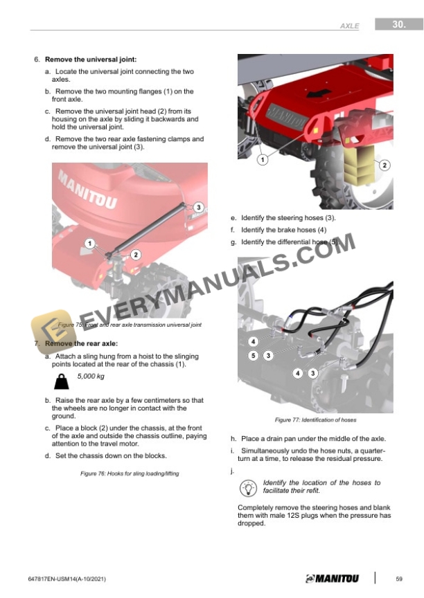
- 20.2. Removing the rear axle
- 21. Refit
- 21.1. Refitting the front axle
- 21.2. Refitting the rear axle
- 22. Section Not Applicable
- 23. Removal
- 23.1. Removing the telescope cylinder slide pads
- 23.2. Removing the arm 3 pads
- 23.3. Removing the moving tube pads
- 24. Refit
- 24.1. Refitting the arm 3 pads
- 24.2. Refitting the moving tube pads
- 25. Characteristics and specifications
- 25.1. List of hydraulic components
- 25.2. PVG32 4T control valve 52711732
- 25.3. PVG32 control valve PVP inlet module
- 25.4. PVG32 control valve PVB(PVLPPVLA) module
- 25.5. PVG32 control valve PVS(LX) outlet module
- 25.6. PVG32 control valve PVEA electrical command module
- 25.7. MA250CDC 016 control valve 685085
- 25.8. Brake Control valve 52653139
- 25.9. Generator valve 52594226
- 25.10. Hydrostatic pump 683966
- 26. Schematics
- 26.1. Hydraulic schematic diagrams
- 27. Location
- 27.1. Location of hydraulic components in the arms
- 27.2. Location of hydraulic components in the chassis
- 27.3. Location of hydraulic components in the turret
- 28. Control and adjustment
- 28.1. Prerequisites for taring proportional distributor
- 28.2. Proportional distributor calibration (PVG324T)
- 28.3. Distributor block calibration turret
- 28.4. Compensating / Tilting circuit
- 28.5. Purging the steering system
- 29. Removal
- 29.1. Removing the proportional valve elements
- 29.2. Removing the Distributor block (turret)
- 29.3. Removing a valve from main valve bank (turret)
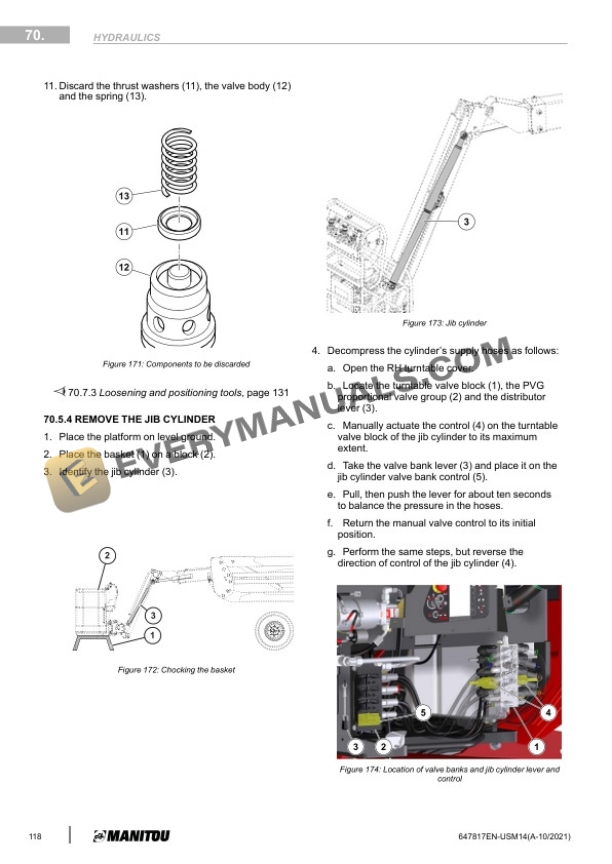
- 29.4. Removing the jib cylinder
- 29.5. Removing the tilting cylinder
- 29.6. Removing the compensating cylinder
- 29.7. Removing the arm 1/2 cylinder
- 29.8. Removing the arm 3 cylinder
- 29.9. Removing the telescope cylinder
- 29.10. Removing the basket rotation cylinder
- 29.11. Removing a cylinder valve block
- 29.12. Removing a valve from a cylinder valve block
- 30. Refit
- 30.1. Installing a valve from main valve bank (turret)
- 30.2. Refitting cylinders
- 31. Specific tools
- 31.1. Digital manometer kit
- 31.2. Basic manometer kit
- 31.3. Loosening and positioning tools
- 32. Characteristics and specifications
- 32.1. Fuses and relays
- 32.2. Technical sheets for electrical components
- 33. Schematics
- 33.1. Electrical Diagram Codification
- 33.2. Electrical marking of cables
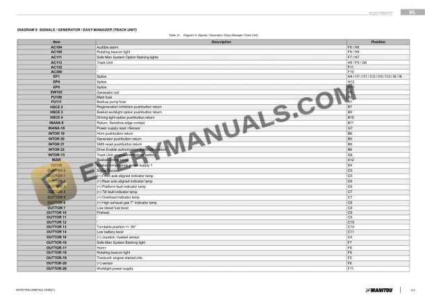
- 33.3. Position of components on electrical diagrams 200 ATJ ST5
- 33.4. Electrical schematic diagram 200 ATJ ST5
- 34. Location
- 34.1. Location of electrical components 200 ATJ ST5
- 34.2. location of electrical harnesses 200 ATJ ST5
- 34.3. Description of electrical harnesses 200 ATJ ST5
- 34.4. Base control panel indicators lamps wiring
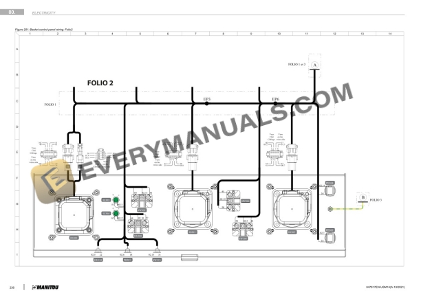
- 34.5. Basket Control Panel Indicators Lamps Wiring
- 35. Control and adjustment
- 35.1. General remarks for adjustment procedures 260TJP/280TJ ST5
- 35.2. Program Operation
- 35.3. Calibrating the manipulators 260TJP/280TJ ST5
- 35.4. Joysticks Testing
- 35.5. Telescope Retracted Sensor Adjustment
- 35.6. Arm down Sensor Adjustment
- 35.7. Tilt Calibration
- 35.8. Overload Sensors Adjustment
- 35.9. Speed calibration
- 35.10. Adjusting the optional generator 260TJP/280TJ ST5
- 35.11. StopGo option management
- 36. Removal
- 36.1. Removing the UC234 card from the base console
- 36.2. Removing UD70 card from base control panel 260TJP/280TJ ST5
- 37. Troubleshooting
- 37.1. Fault Codification
- 37.2. List of Alert and Default Codes
- 37.3. List of Alert and Default Codes (Refer to Section 120)
- 38. Specific tools
- 38.1. Breakout boxes
- 39. Section Not Applicable
- 40. Control and adjustment
- 40.1. Controlling the slewing ring gear play 200ATJ ST5
- 41. Location
- 41.1. Location of SPS components
- 41.2. Description of electrical harnesses SPS option
- 42. Control and adjustment
- 42.1. Adjusting Sensor cable
- 43. DTC error codes for mobile elevating platforms (Yanmar ST5)
- 43.1. Generic SPN prefixes
- 43.2. Generic FMI suffixes
- 43.3. Complete DTC codes
- 44. Diagnostics Case (MEWP)
- 44.1. Contents of reprogramming case
- 44.2. Individual reprogramming of ECUs file .H86
- 44.3. Individual reprogramming of ECUs file .H86
- 44.4. Individual reprogramming of ECUs file .HQX
- 44.5. Individual reprogramming of ECUs file .HQX
- 44.6. Reprogramming via CAN BUS connection to the UPC30
- 44.7. Reprogramming via CAN BUS connection to the base control panel