
Description
-
Model List:
- TMT 55 HT K T4 S3
- TMT 55 XT 4W K T4 S3
- TMT 55 XT K T4 S3
- TMT 55 XT 4W K T4 S3
- 1. Legal disclaimer
- 2. Foreword
- 3. List of Abbreviations
- 4. Intervention during the warranty period
- 5. Servicing Rules
- 6. Explanation of symbols
- 7. Servicing position
- 8. Third party documentation list TMT HTXT T4
- 9. Characteristics and specifications
- 9.1. Technical data sheet TMT 55 HT K T4 S3
- 9.2. Technical data sheet TMT 55 HT 4W K T4 S3
- 9.3. Technical data sheet TMT 55 XT K T4 S3
- 9.4. Technical data sheet TMT 55 XT 4W K T4 S3
- 9.5. Lubricants fuels TMT HT XT 4W Tier4
- 10. Location
- 10.1. Location of name and identification plates TMT ST5
- 11. Control and adjustment
- 11.1. Standard tightening torques
- 11.2. Metric imperial unit conversion
- 12. Characteristics and specifications
- 12.1. General characteristics Kubota D1803CRTE4
- 13. Location
- 13.1. Locating engine components TMT 55 HT XT
- 14. Removal
- 14.1. Preparation and safety instructions
- 14.2. Engine removal TMT 55 HT XT
- 14.3. Air cooling radiator removal
- 14.4. Water cooling radiator removal TMT HT XT
- 15. Refit
- 15.1. Refitting the components
- 16. Flow diagrams and schematic diagrams
- 16.1. Hydrostatic schematic diagram Forward TMT ST5
- 16.2. Hydrostatic schematic diagram Reverse TMT ST5
- 16.3. Hydrostatic schematic diagram Forward TMT 4W ST5
- 16.4. Hydrostatic schematic diagram Reverse TMT 4W ST5
- 17. Location
- 17.1. Location of hydrostatic components
- 17.2. Location of steering components
- 18. Control and adjustment
- 18.1. Requirements for hydrostatic adjustmentsA4VG56A10VG45TJ
- 18.2. Location of the hydrostatic transmission pump pressure ports
- 18.3. Transmission hydrostatic pump pressure values
- 18.4. Tractive force adjustment
- 18.5. Adjust the hydrostatic pump to advance the carriage
- 18.6. Hydrostatic transmission settings sheet A4VG pump
- 18.7. Towing the truck TMM/TMT ST5
- 18.8. Tightening torques for hydrostatic pump A4VG40DA
- 18.9. Tightening torques for Flow divider 4W_B03045556
- 18.10. Tightening torque for steering selection unit 4 Way
- 18.11. Tightening torques for rear wheel motor TMM/TMT ST5
- 18.12. Tightening torques for front wheel motor TMM/TMT ST5
- 19. Removal
- 19.1. Hydrostatic pump removal
- 19.2. Steering block removal
- 19.3. Remove the front wheel motor TMT ST5
- 19.4. Removing the front wheel motor TMM/TMT ST5 4 Way
- 19.5. Removing the rear wheel motor TMM/TMT ST5
- 19.6. Rear steering cylinder removal
- 19.7. Front steering cylinder removal 4 Way
- 19.8. Steering mode selection unit BSD removal 4 Way
- 19.9. INV HP Shuttle unit removal 4 Way
- 20. Specific tooling
- 20.1. Basic manometer kit
- 20.2. Digital manometer kit
- 21. Characteristics and specifications
- 21.1. Pivot characteristics
- 22. Location
- 22.1. Rear pivot components location
- 22.2. Front pivot components location
- 23. Removal
- 23.1. Rear pivot removal
- 23.2. Front pivot removal 4 Way
- 24. Refit
- 24.1. Refitting the rear pivot
- 25. Location
- 25.1. Location of brake components
- 26. Control and adjustment
- 26.1. Adjust the service brake pedal and transmission cutoff (inc
- 26.2. Tightening torques (hydraulics) TH7 valve
- 26.3. Tightening torques (Hydraulic) Steering unit Orbitrol
- 27. Removal
- 27.1. TH7 valve removal
- 28. Characteristics and specifications
- 28.1. Composition of the duplex boom
- 29. Location
- 29.1. Boom location
- 30. Control and adjustment
- 30.1. Preparation and safety instructions
- 30.2. Tilting cylinder removal
- 30.3. Refitting crowd cylinder
- 30.4. Carriage removal
- 30.5. Carriage reassembly
- 30.6. Boom extension cylinder removal
- 30.7. Refitting the boom extension cylinder
- 30.8. Telescope removal
- 30.9. Refit the telescope
- 30.10. Side shift cylinder removal
- 30.11. Side shift cylinder reassembly
- 30.12. Boom cross sections / Slide pad adjustments
- 31. Removal
- 31.1. Preparation and safety instructions
- 31.2. Boom removal
- 32. Refit
- 32.1. Preparation and safety instructions
- 32.2. Boom refit
- 33. Flow diagrams and schematic diagrams
- 33.1. Hydraulic schematic diagram (TMT 25S 27P)
- 33.2. Hydraulic schematic diagram (TMT 25S 4W)
- 34. Location
- 34.1. Location of main hydraulic circuit steering telescoping
- 34.2. Braking hydraulic circuit location oil cooling TMT
- 34.3. Location of the hydraulic circuit self loading kit Hydra
- 34.4. Location of the boom compensation hydraulic circuit 4 Way
- 35. Control and adjustment
- 35.1. Bleed the front steering cylinders 4 Way Display control
- 35.2. Fitting distributor tightening torques TMT
- 35.3. Tightening torques hydraulic distributor walvoil SD6_10DA4
- 35.4. Tightening torques for hydrostatic pump A4VG40DA
- 35.5. Tightening torques for hydraulic pump TMT
- 35.6. tightening torques for stabilizer valve TMT 4W
- 35.7. Tightening torques of the folding arm solenoid valve (option
- 36. Removal
- 36.1. Remove foldable arm electrovalve (option) TMT
- 37. Specific tooling
- 37.1. Basic manometer kit
- 37.2. Digital manometer kit
- 38. Characteristics and specifications
- 38.1. Electronic module E18/S6
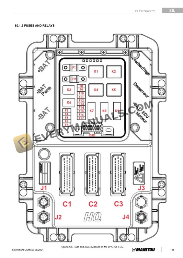
- 38.2. Fuses and Relays
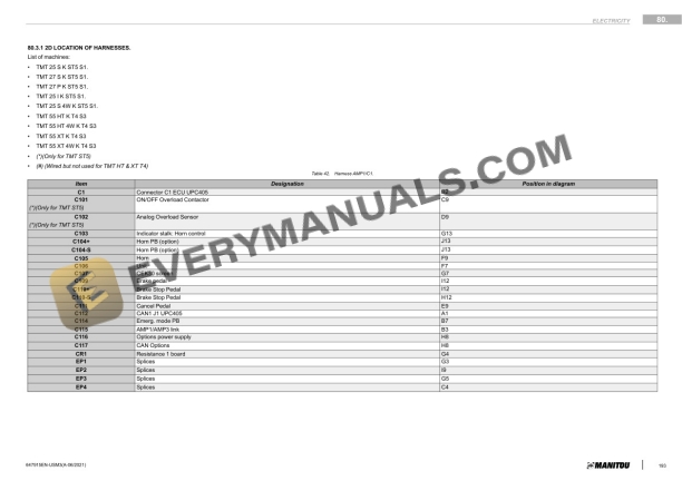
- 38.3. Connectors TMT ST5
- 39. Flow diagrams and schematic diagrams
- 39.1. Electrical marking of cables
- 39.2. Electrical schematic diagram TMT ST5
- 40. Location
- 40.1. Location of main electrical harness components TMT ST5
- 40.2. Location of main electrical harness components TMT ST5
- 40.3. Location of 4 Way electrical harness TMT 4W ST5
- 40.4. Location of 4 Way electrical harness components TMT ST5
- 41. Troubleshooting
- 41.1. Navigate the driving screen menus TMT
- 41.2. Faults and alerts screen pages
- 41.3. Troubleshooting on the 4 Way module
- 42. TMT malfunction codes
- 42.1. Fault icon
- 42.2. List of malfunctions
- 43. Diagnostics tools Kubota DIAGMASTER (DSTi)
- 43.1. KUBOTA engine diagnostics tool Diagmaster
- 44. Diagnostics Codes (Kubota 1803CRE5B)
- 45. Diagnostics Codes After Treatment (Kubota 1803CRE5B)
- 46. Pocket for E18/S6 module
- 46.1. Pocket for the E18/S6 electronic module.
- 46.2. Pocket front panel
- 46.3. Coding on the digital display of the Pocket unit
- 46.4. Coding on the digital display of the Pocket unit
- 46.5. Pocket operating diagram
- 46.6. Use of the Pocket unit