
Description
-
Model List:
- DN495 G5 Dry Spinner Spreader
- 1. Introduction
- 1.1. Foreword
- 1.2. Predelivery
- 1.3. Delivery
- 1.4. AfterSale
- 1.5. Owner Register
- 1.6. Component Identification
- 1.7. Recognize Safety Information
- 1.8. Understand Signal Words
- 1.9. Follow Safety Instructions
- 1.10. Prepare for Emergencies
- 1.11. Wear Protective Clothing
- 1.12. Protect Against Noise
- 1.13. Practice Safe Maintenance
- 1.14. Park Machine Safely
- 1.15. Remove Paint Before Welding or Heating
- 1.16. Avoid Heating Near Pressurized Fluid Lines
- 1.17. Avoid HighPressure Fluids
- 1.18. Decommissioning Proper Recycling and Disposal of Fluids and Components
- 1.19. Handle Chemical Products Safely
- 1.20. Service Spreader Equipment Safely
- 1.21. Use Proper Tools
- 1.22. Work In Ventilated Area
- 1.23. Handling Batteries Safely
- 1.24. Service Drive Belts Safely
- 1.25. Using Compressed Air For Cleaning
- 1.26. Maintain a Safety Area Around the Machine
- 1.27. Working Area
- 1.28. Avoid Backover Accidents
- 1.29. Before Operating
- 1.30. Operate Safely
- 1.31. Avoid Injury from Thrown Objects
- 1.32. Use Safety Lights and Devices
- 1.33. Keep Riders Off Machine
- 1.34. Passenger Seat
- 1.35. Use Steps and Handholds Correctly
- 1.36. Use Seat Belt Properly
- 1.37. Use Caution On Hillsides
- 1.38. Transport and Operate Safely
- 1.39. Prevent Machine Runaway
- 1.40. Handle Fuel SafelyAvoid Fires
- 1.41. Handle Agricultural Chemicals Safely
- 1.42. Spreading Dusty Materials
- 1.43. Avoid Exposure To Chemicals
- 1.44. Clean Vehicle of Hazardous Chemicals, Including Pesticides
- 1.45. NonPermissible Use
- 1.46. Emergency Exit
- 2. Safety Signs Location
- 2.1. Replace Safety Signs
- 2.2. Conveyor Cover Decal
- 2.3. Spreader Front Decal (If Applicable)
- 2.4. LeftHand Rear Side Decals
- 2.5. LeftHand Front Decal
- 2.6. Roll Tarp Decals (If Equipped)
- 2.7. LeftHand Front Corner Decals
- 2.8. Fender Decal
- 2.9. RightHand Rear Corner DecalsSingle Bin
- 2.10. RightHand Rear Corner DecalsSecond Product Bin
- 2.11. RightHand Rear Side Decals
- 2.12. RightHand Front Corner Decals
- 2.13. Rear DecalsMultiBin
- 2.14. Top Side DecalMultiBin
- 3. Installation Instructions
- 3.1. Hose Installation Guide
- 3.2. Install Beacon Light KitIf Equipped
- 3.3. Install Inverted V
- 3.4. Install Second Product BinSpreaders with Belt Over Chain Conveyors
- 3.5. Install Second Product Bin Hillside Divider
- 3.6. Install Dual Conveyor Cover
- 3.7. Install Micronutrient Bin Hillside Divider
- 3.8. Install Micronutrient Bin Cover
- 3.9. Install StarFire Receiver Bracket (EU Exports Only)
- 3.10. Install Speed Limit Decal
- 3.11. Remove Second Product Bin and Install Endgate
- 4. Safety Features
- 4.1. Safety Features
- 5. Controller Operations
- 5.1. Introduction
- 5.2. How the ISOBUS Works
- 5.3. Terminologies
- 5.4. Diagrams
- 5.5. Requirements
- 5.6. Navigation
- 5.7. Machine Configuration
- 5.8. Settings
- 5.9. Material Profile Management
- 5.10. Component Calibration
- 5.11. Operation / Features
- 5.12. Diagnostics
- 5.13. Hydraulics
- 5.14. Bin Flush
- 5.15. Body Module
- 5.16. Chain Oiler
- 5.17. Bin Sequencing
- 5.18. General Alarms
- 5.19. General Product Control Alarms
- 5.20. Spinner Alarms
- 5.21. Fan Frame Alarms
- 5.22. Feed Gate Alarm
- 5.23. Hydraulic Alarms
- 5.24. Default Settings
- 5.25. Calibration Settings
- 5.26. Alarm Settings
- 5.27. Product Setup Guidelines
- 6. PreStarting Checks
- 6.1. Informational Decals
- 6.2. Verify Material Divider Position
- 6.3. Install Material DeflectorOptional
- 6.4. Verify Spinner Fin Installation
- 6.5. Verify Spinner Speed Sensor Gap
- 6.6. Verify Hillside Divider Location
- 6.7. Verify Correct Chain TensionBelt Over Chain Conveyor Only
- 6.8. Verify Second Product Bin Hillside Divider Location
- 7. Operate System
- 7.1. Control Switch Box Component Identification
- 7.2. Initial StartUp
- 7.3. Field Test
- 7.4. Spreader System Check
- 7.5. Setup Display
- 7.6. General Operation Process
- 8. Size Grading and Hardness Test
- 8.1. Introduction
- 8.2. Crush Strength
- 8.3. Hardness Test
- 8.4. Size Grade Number
- 8.5. Size Grade Number Scale
- 9. Spread Pattern
- 9.1. Spread Pattern Adjustment
- 9.2. Spinners
- 9.3. Spreader Preparation
- 9.4. Determine Material Bulk Density
- 9.5. Determine Material CFR
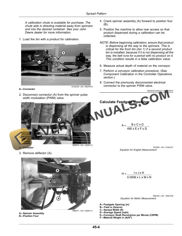
- 9.6. Calculate Feedgate Opening
- 9.7. Spread Pattern Test Procedure
- 9.8. Troubleshooting
- 10. Lubrication and Maintenance
- 10.1. Clean Vehicle of Hazardous Chemicals, Including Pesticides
- 10.2. Prevent Hydraulic System Contamination
- 10.3. Dispose of Waste Properly
- 10.4. Service Intervals
- 10.5. Conveyor CleanoutAs Required
- 10.6. Belt Over Chain Conveyor Maintenance and AdjustmentAs Required
- 10.7. Install Replacement Spreader FinsAs Required
- 10.8. Clean Bin SensorAs Required
- 10.9. Remove Meter RollersAs Required
- 10.10. Inspect TarpBiweekly (If Equipped)
- 10.11. Inspect Tarp Assembly HardwareBiweekly (If Equipped)
- 10.12. Check Tarp Assembly Cable TensionBiweekly (If Equipped)
- 10.13. Lubricate Belt Over Chain ConveyorDaily
- 10.14. Lubricate Idler Shaft Bearings and Adjustment ScrewsWeekly
- 10.15. Lubricate Drive Shaft BearingsWeekly
- 10.16. Lubricate Spinner JackWeekly
- 10.17. Lubricate Second Product Bin Drive and Idler Shaft BearingsWeekly
- 10.18. Lubricate Feedgate Jack Tube (If Equipped)Weekly
- 10.19. Check Gear Case OilMonthly
- 10.20. Lubricate Meter Roller Drive Chains
- 10.21. Change Gear Case OilAnnually
- 10.22. Lubricate Feedgate Jack Gears (If Equipped)Annually
- 10.23. Lubricate Second Product Bin Idler Adjustment ScrewsAnnually
- 11. Lubricant Specifications
- 11.1. Transmission and Hydraulic Oil
- 11.2. Gear Case Oil
- 11.3. Multipurpose Extreme Pressure (EP) Grease
- 11.4. Chain Oiler Mixture
- 12. Troubleshooting
- 12.1. Troubleshooting
- 12.2. Schematics
- 13. Storage
- 13.1. Avoid Exposure To Chemicals
- 13.2. Clean Vehicle of Hazardous Chemicals, Including Pesticides
- 13.3. Prepare Machine for Storage
- 13.4. Remove Machine from Storage
- 14. Specifications
- 14.1. Specifications
- 14.2. Dimensions
- 14.3. Unified Inch Bolt and Screw Torque Values
- 14.4. Metric Bolt and Screw Torque Values
- 14.5. Face Seal Fittings Assembly and InstallationAll Pressure Applications
- 14.6. Metric Face Seal and ORing Stud End Fitting Torque ChartStandard Pressures
- 14.7. Metric Face Seal and ORing Stud End Fitting Torque ChartHigh Pressure Applications
- 14.8. SAE Face Seal and ORing Stud End Fitting Torque ChartStandard Pressures
- 14.9. SAE Face Seal and ORing Stud End Fitting Torque ChartHigh Pressure Applications
- 14.10. Four Bolt Flange Fittings Assembly and InstallationAll Pressure Applications
- 14.11. SAE Four Bolt Flange Cap Screw Torque ValuesStandard Pressure Applications
- 14.12. SAE Four Bolt Flange Cap Screw Torque ValuesHigh Pressure Applications
- 14.13. External Hexagon Port Plug Torque Chart
- 14.14. Identification Numbers
- 14.15. Interpret the Serial Number of Your Machine 17 digits PIN
- 14.16. Year of Production Table (Digit 5)
- 14.17. Keep Proof of Ownership
- 14.18. Keep Machines Secure
- 15. John Deere Service Literature Available
- 15.1. Technical Information
- 16. John Deere Service Keeps You On The Job
- 16.1. John Deere Parts
- 16.2. The Right Tools
- 16.3. WellTrained Technicians
- 16.4. Prompt Service




