
Description
-
Model List:
- 1520 Integral Grain Drill
- 1. Introduction
- 1.1. Foreword
- 1.2. A Message to Our Customers
- 1.3. Integral Grain Drill
- 1.4. Recognize Safety Information
- 1.5. Understand Signal Words
- 1.6. Follow Safety Instructions
- 1.7. Operate the Machine Safely
- 1.8. Keep Riders Off Machine
- 1.9. Prepare for Emergencies
- 1.10. Wear Protective Clothing
- 1.11. Handle Agricultural Chemicals Safely
- 1.12. Use Safety Lights and Devices
- 1.13. Avoid Tipovers
- 1.14. Tow Loads Safely
- 1.15. Charge Row Marker Hydraulic System
- 1.16. Use Steps and Handholds Correctly
- 1.17. Operator Ability
- 1.18. Service Machine Safely
- 1.19. Practice Safe Maintenance
- 1.20. Remove Paint Before Welding or Heating
- 1.21. Avoid Heating Near Pressurized Fluid Lines
- 1.22. Avoid HighPressure Fluids
- 1.23. Store Attachments Safely
- 1.24. Decommissioning Proper Recycling and Disposal of Fluids and Components
- 1.25. Inspect Lift Circuit Hoses
- 1.26. Replace Safety Signs
- 1.27. Safety Features
- 2. Safety Signs
- 2.1. Transport Guidelines
- 2.2. Sudden Crushing Movement
- 2.3. Electric Line Contact
- 2.4. Falling from Height
- 2.5. Sudden Crushing Movement
- 2.6. Falling Marker
- 2.7. Chemical Contact
- 2.8. Falling from Height
- 3. Information Decals
- 3.1. Information Decals
- 4. Preparing the Tractor
- 4.1. Use Your Tractor Operators Manual
- 4.2. Setting Wheel Tread
- 4.3. Sway Blocks
- 4.4. Link Lengths
- 4.5. Check Tire Inflation
- 4.6. Hitch Load/Depth Control
- 4.7. Drill Implement Codes
- 4.7.1. Example
- 4.8. Tractor Hitch Lift Codes (Fully Mounted Drill)
- 4.9. Tractor Front Ballast Codes (Fully Mounted Drill)
- 4.10. Tractor Rear Tire Compatibility
- 4.11. Load Added to Tractor Rear Axle When Lifting 1520 Drill
- 4.12. Lever Lock Clip (4060 Series Row Crop Tractors)
- 4.13. Setting Selective Control Valve (4060 Series Row Crop Tractors)
- 4.14. Setting Rockshaft Drop Rate (4060 Series Row Crop Tractors)
- 4.15. Setting Selective Control Valve and Rockshaft (7000 Series Tractors)
- 4.16. Setting Selective Control Valves and Rockshaft (8000 Series Tractors)
- 5. Preparing the Grain Drill
- 5.1. Tighten Hardware
- 5.2. Marker Safety Bolt
- 5.3. Tighten Wheel Bolts
- 5.4. Check Tire Pressure
- 5.5. Lubricate Grain Drill
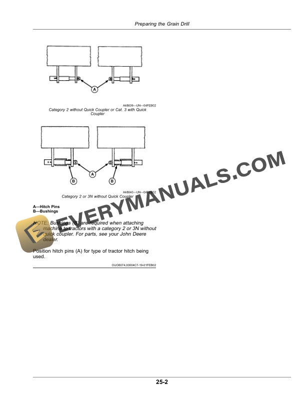
- 5.6. Positioning Rockshaft Hitch Pins
- 6. Attaching and Detaching
- 6.1. Attach Grain Drill to Tractor (with QuickHitch)
- 6.2. Attach Grain Drill to Tractor (without QuickHitch)
- 6.3. Detach Grain Drill from Tractor
- 7. Transporting
- 7.1. Transport Safely
- 7.2. Lighting and Marking
- 7.3. Light Enhancement Module
- 7.4. Marker Transport Lock
- 8. Operating the Grain Drill
- 8.1. Guidelines for Use
- 8.2. Leveling the Machine
- 8.3. Changing Gauge Wheel Position
- 8.4. Leveling Marker
- 8.5. Adjust Marker Length
- 8.6. Adjust Marker Furrow
- 8.7. Marker Float Range
- 8.8. Adjust Opener Downforce (Machines without Hydraulic Downforce)
- 8.9. Adjust Opener Downforce (Machines with Hydraulic Downforce)
- 8.10. Adjust Individual Opener Downforce
- 8.11. Adjust Seed Depth
- 8.12. Adjusting DoubleDisk Outside Scrapers
- 8.13. Check Disk BladesAluminum Boot
- 8.14. Check Fluted Grain Feeds
- 8.15. Set FlutedFeed Grain Shifter
- 8.16. Use Seed Mixtures
- 8.17. Cleaning and Setting FlutedFeed Cups
- 8.18. Setting HalfSpeed Drive Shaft Speed
- 8.19. DoubleSpeed Drive Attachment Assembly
- 8.20. FlutedFeed Seed Charts
- 8.21. Using Kilograms of Seed Per Hectare Chart
- 8.22. Using Pounds of Seed Per Acre Chart
- 8.23. Use Density Meter and FlutedFeed Seed Charts
- 8.24. Grain Seed Rate Chart15 cm Rows
- 8.25. Grain Seed Rate Chart6 Inch Rows
- 8.26. Grain Seed Rate Chart19 cm Rows
- 8.27. Grain Seed Rate Chart7.5 Inch Rows
- 8.28. Grain Seed Rate Chart25 cm Rows
- 8.29. Grain Seed Rate Chart10 Inch Rows
- 8.30. Check Feeds (Machines with Grass Seed Attachment)
- 8.31. Set Feed Shifter (Machines with Grass Seed Attachment)
- 8.32. Use Grass Seed Mixtures
- 8.33. Use Grass Seed Charts
- 8.34. Use Density Meter and Grass Seed Charts
- 8.35. Grass Seed Rate Chart15 cm Rows
- 8.36. Grass Seed Rate Chart6 Inch Rows
- 8.37. Grass Seed Rate Chart19 cm Rows
- 8.38. Grass Seed Rate Chart7.5 Inch Rows
- 8.39. Grass Seed Rate Chart25 cm Rows
- 8.40. Grass Seed Rate Chart10 Inch Rows
- 8.41. Importance of Checking Quantities Drilled
- 8.42. Check Quantities DrilledMethod 1
- 8.43. Check Quantities DrilledMethod 2
- 8.44. Drilling Row Crops
- 9. Attachments
- 9.1. Adjusting Depth Gauging Press Wheels
- 9.2. Grass Seed Attachment
- 9.3. Grain Feed StopFluted Feeds
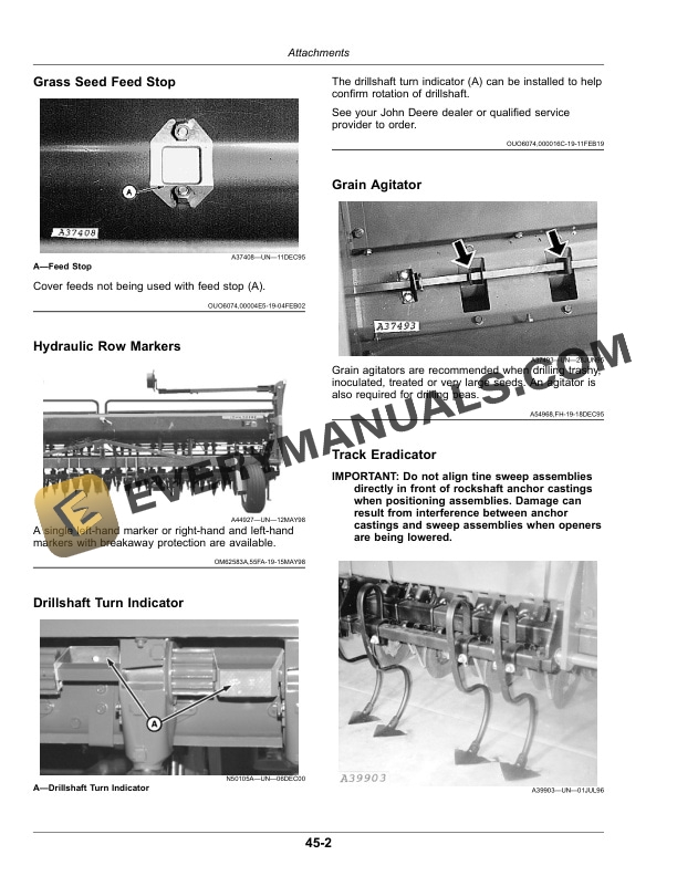
- 9.4. Grass Seed Feed Stop
- 9.5. Hydraulic Row Markers
- 9.6. Drillshaft Turn Indicator
- 9.7. Grain Agitator
- 9.8. Track Eradicator
- 9.9. Open Center Kit
- 9.10. Tire Options
- 10. Lubrication and Maintenance
- 10.1. Multipurpose Extreme Pressure (EP) Grease
- 10.2. Alternative and Synthetic Lubricants
- 10.3. Lubrication Symbols
- 10.4. Lubricant Storage
- 10.5. Roller Chain Lubrication
- 10.6. Lubrication Points
- 11. Troubleshooting
- 11.1. Troubleshooting
- 12. Servicing
- 12.1. Metric Bolt and Screw Torque Values
- 12.2. Unified Inch Bolt and Screw Torque Values
- 12.3. Metric Face Seal and ORing Stud End Fitting Torque ChartStandard Applications
- 12.4. Metric Face Seal and ORing Stud End Fitting Torque ChartHeavyDuty Applications
- 12.5. SAE Face Seal and ORing Stud End Fitting Torque ChartStandard Applications
- 12.6. SAE Face Seal and ORing Stud End Fitting Torque ChartHeavyDuty Applications
- 12.7. FaceSealFitting Assembly and InstallationAll Pressure Applications
- 12.7.1. FaceSeal ORing to Stud End Installation
- 12.7.2. FaceSeal Adjustable Stud End ORing Installation
- 12.7.3. FaceSeal Straight Stud End ORing Installation
- 12.7.4. Fitting Installation
- 12.7.5. Assembly Torque
- 12.8. Avoid HighPressure Fluids
- 12.9. Service Tires Safely
- 12.10. Practice Safe Maintenance
- 12.11. Welding Near Electronic Control Units
- 12.12. Keep Electronic Control Unit Connectors Clean
- 12.13. Blocking Machine in Raised Position
- 12.14. Lock Up Openers
- 12.15. Removing and Repairing Cylinders
- 12.16. Bleeding Trapped Air from Cylinders
- 12.17. Reset FlutedFeed Cups
- 12.18. Check Feed Shaft Rolling Torque
- 12.19. Replace and Adjust DoubleDisk Blades on Aluminum Boots
- 12.20. Replace Inside Scrapers
- 12.21. Replacing Seed TubesDoubleDisk Opener
- 12.22. Gauge Wheel Drive Shear Pin
- 12.23. Replace Marker Breakaway Bolt
- 12.24. Ratchet Drive
- 12.25. Hydraulic Location Drawing LeftHand Marker Only
- 12.26. Marker Hydraulic Location Drawing
- 12.27. Hydraulic Downforce Drawing4.6 m (15 ft)
- 12.28. Hydraulic Downforce Drawing6.1 m (20 ft)
- 13. Storing
- 13.1. Preparing Machine for Storage
- 13.2. Removing Machine from Storage
- 14. Specifications
- 14.1. Machine Specifications
- 14.2. Record Serial Number
- 14.3. Keep Proof of Ownership
- 14.4. Keep Machines Secure
- 15. John Deere Service Keeps You on the Job
- 15.1. John Deere Parts
- 15.2. The Right Tools
- 15.3. WellTrained Technicians
- 15.4. Prompt Service




