Description
-
Model List:
- 78 SEC 2
- 100 SEC 2
- 120 SE 2
- 1. Page de garde 647188201910
- 2. GENERAL SOMMAIRY
- 3. GENERAL, CHARACTERISTICS AND SAFETY
- 3.1. GENERAL INSTRUCTIONS AND SAFETY ADVICE
- 3.1.1. General instructions
- 3.1.2. Replacement parts
- 3.1.3. Technical documentation
- 3.1.4. Repairs procedures
- 3.1.5. HYDRAULIC COMPONENTS
- 3.1.6. symbols
- 3.1.7. EQUIPMENT REQUIRED
- 4. AXLE
- 4.1. AXLE REMOVAL
- 4.1.1. Yoke and Drive Motor
- 4.1.2. Steer Cylinder
- 4.1.3. Steer Bellcrank
- 5. BRAKE
- 5.1. BRAKE REMOVAL
- 5.1.1. Drive Brake
- 5.1.2. Brake Release Hand Pump Components
- 6. BOOM
- 6.1. JIB ACCESS PLATFORM REMOVAL
- 6.1.1. Platform
- 6.1.2. Platform Extension
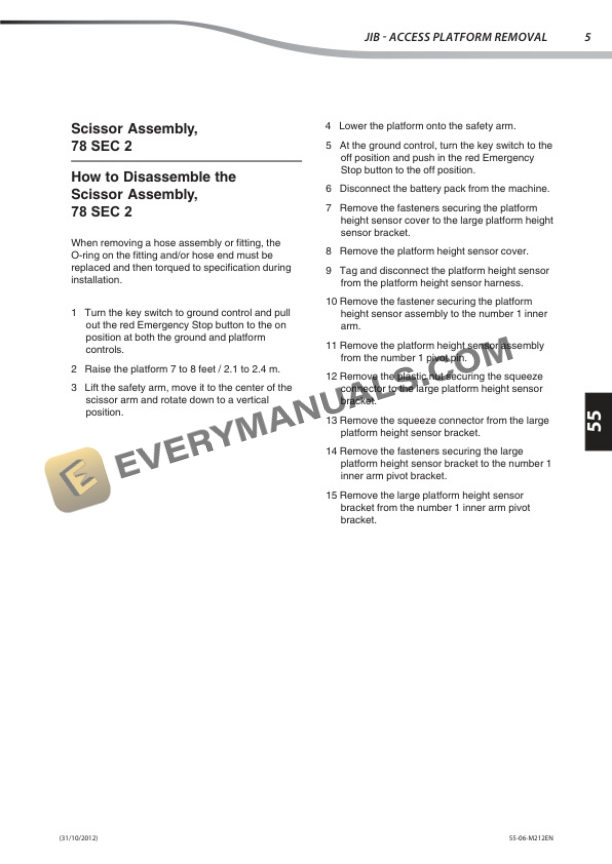
- 6.1.3. Scissor Assembly,78 SEC 2
- 6.1.4. How to Replace the Scissor ArmWear Pads
- 6.1.5. Scissor Assembly,100 SEC 2
- 6.1.6. How to Replace the Scissor ArmWear Pads
- 6.1.7. Scissor Assembly,120 SE 2
- 6.1.8. How to Replace the Scissor ArmWear Pads
- 6.1.9. Manual Platform Lowering Cable
- 7. HYDRAULIC
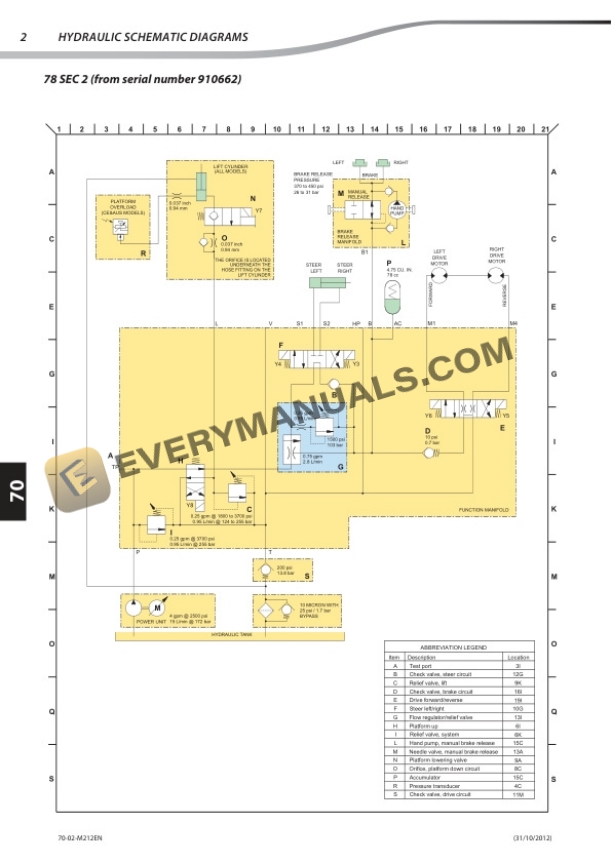
- 7.1. HYDRAULIC SCHEMATIC DIAGRAMS
- 7.1.1. SEC 2 (from serial number 910662)
- 7.1.2. SEC 2 (from serial number 917098)120 SE 2 (from serial number 915526)
- 7.2. HYDRAULIC CONTROL AND ADJUSTMENT
- 7.2.1. Function Pump
- 7.2.2. Function Manifold Components 78 SEC 2
- 7.2.3. Function Manifold Components 100 SEC 2 120 SE 2
- 7.2.4. Check Valve Manifold Components 78 SEC 2
- 7.2.5. Valve Adjustments Function Manifold
- 7.2.6. How to Adjust thePlatform Lift Relief Valve
- 7.2.7. How to Adjust the Steer ReliefValve
- 7.3. HYDRAULIC COMPONENTS REMOVAL
- 7.3.1. Lift Cylinder
- 7.3.2. How to Remove theHydraulic Pump
- 7.3.3. Hydraulic Tank
- 8. ELECTRIC
- 8.1. Electrical schematic diagrams
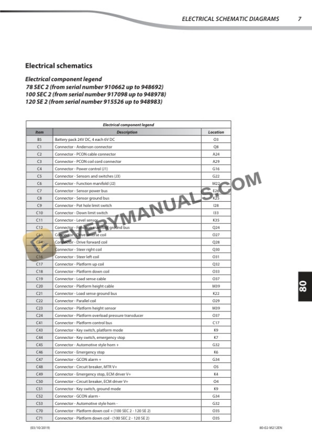
- 8.1.1. Legends
- 8.1.2. Electrical schematics
- 8.2. ELECTRICAL CONTROL AND ADJUSTMENT
- 8.2.1. Platform controls
- 8.2.2. Circuit Board
- 8.2.3. Joystick
- 8.2.4. Platform Controls Alarm
- 8.2.5. Platform Emergency Stop Button
- 8.2.6. Scissor components
- 8.2.7. Platform Overload System
- 8.2.8. Platform Overload RecoveryMessage
- 8.2.9. Ground controls
- 8.2.9.1. Software Revision Level
- 8.2.9.2. Machine Setup
- 8.2.9.3. Display Menu
- 8.2.9.4. Service Override Mode
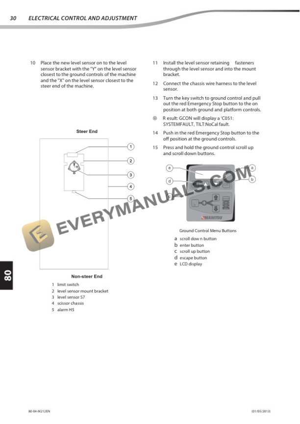
- 8.2.9.5. Level Sensors
- 8.2.9.6. Manifolds
- 8.2.9.6.1. How to Test a Coil Diode
- 8.3. ELECTRICAL TROUBLESHOOTING
- 8.3.1. Type HXXX Faults
- 8.3.2. Type PXXX Faults
- 8.3.3. Type UXXX Faults
- 8.3.4. Type FXXX Faults
- 8.3.5. Type CXXX Faults
- 8.3.6. Battery Charger
- 8.3.6.1. Charger Error Codes