
Description
-
Model List:
- ATJ 46 T4 S2
- 1. Legal disclaimer
- 2. Foreword
- 3. Intervention during the warranty period
- 4. Supplier Documentation List
- 5. Safety
- 5.1. Servicing Rules
- 6. Machine Service Operations
- 6.1. Servicing position
- 6.2. Preparation and safety instructions MEWP
- 7. Characteristics and specifications
- 7.1. Technical Data Sheet (ATJ 46 T4 S2)
- 7.2. Machine Dimensions (ATJ 46 T4 S2)
- 7.3. Lubricants and Fuel
- 8. Reference information
- 8.1. Explanation of symbols
- 8.2. List of Abbreviations
- 8.3. Standard tightening torques
- 8.4. Metric imperial unit conversion
- 9. Characteristics and specifications
- 9.1. Supplier Documentation
- 9.2. General characteristics Kubota D1105E4B
- 10. Location
- 10.1. Location of engine components Kubota D1105E4B
- 10.2. Fuel Circuit Component Location
- 11. Control and adjustment
- 11.1. Engine Tightening Torques
- 11.2. Adjusting the Proportional Engine Speed Block
- 11.3. alternator belt tension adjustment
- 12. Removal
- 12.1. Setting up the Crutch
- 12.2. Engine Access Covers Removal
- 12.3. Cooling System Removal
- 12.4. Removing the Silencer
- 12.5. Harnesses Removal
- 12.6. Removal of Air Intake Circuit
- 12.7. Removal of Fuel Circuit
- 12.8. Hoses Removal for Hydrostatic and Auxiliary Pump
- 12.9. Proportional Engine Speed Block Removing
- 12.10. Engine Removal
- 13. Refit
- 13.1. Installing Engine Components
- 14. Troubleshooting
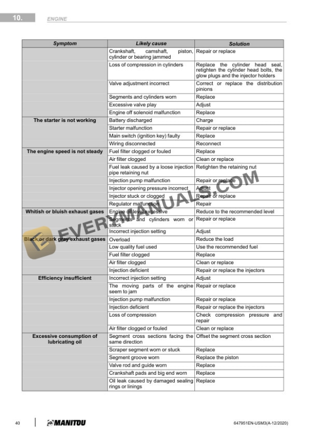
- 14.1. Engine Troubleshooting Details
- 14.2. Engine Diagnostic Codes (Refer to Section 120)
- 15. Characteristics and specifications
- 15.1. Supplier Documentation
- 16. Location
- 16.1. Transmission Components Location
- 17. Control and adjustment
- 17.1. Transmission Tightening Torques
- 17.2. Location of Pressure Ports (A10VG Rexroth Pump)
- 17.3. Location of Adjustment Points (A10VG Rexroth Pump)
- 17.4. Calibration of LP Booster Valve
- 17.5. Adjustment of the Neutral Point Servo Control Piston
- 17.6. Calibration of HP Valves
- 17.7. Calibration of Zero Flow Valve DR
- 18. Removal
- 18.1. Removing the Hydrostatic Pump
- 18.2. Removing the Hydrostatic Motor
- 19. Refit
- 19.1. Installing the Hydrostatic Pump
- 19.2. Installing the Hydrostatic Motor
- 20. Characteristics and specifications
- 20.1. Supplier Documentation
- 21. Control and adjustment
- 21.1. Freewheel Operation
- 22. Removal
- 22.1. Removing the Front Axle
- 22.2. Removing the Rear Axle
- 23. Refit
- 23.1. Refitting the Front and Rear Axles
- 24. Section Not Applicable
- 25. Removal
- 25.1. Removing the Telescope Cylinder Slide Pads
- 25.2. Removing the Arm 3 Pads
- 25.3. Removing the Moving Tube Pads
- 25.4. Removing the Basket
- 25.5. Removing the Jib
- 26. Characteristics and specifications
- 26.1. Supplier Documentation
- 27. Flow diagrams and schematic diagrams
- 27.1. Hydraulic Schematic Diagram
- 28. Location
- 28.1. Location of Hydraulic Components in the Chassis
- 28.2. Location of Hydraulic Components in the Turntable
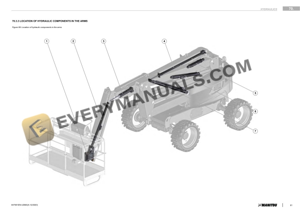
- 28.3. Location of Hydraulic Components in the Arms
- 29. Control and adjustment
- 29.1. Prerequisites for Taring Proportional Distributor
- 29.2. Proportional Distributor Calibration (PVG324T)
- 29.3. Distributor Block Calibration
- 29.4. Compensating Tilting Circuit
- 30. Removal
- 30.1. Removing the elements of Proportional Distributor
- 30.2. Removing the Distributor block
- 30.3. Removing Distributor Block Valve
- 30.4. Prerequisites for Cylinder Removal
- 30.5. Hose Decompression
- 30.6. Removing the Cylinders
- 30.7. Removing Valve Blocks and Valves
- 31. Refit
- 31.1. Refitting Distributor Block Valve
- 31.2. Refitting Cylinders
- 32. Specific tooling
- 32.1. Digital manometer kit
- 32.2. Basic manometer kit
- 33. Characteristics and specifications
- 33.1. Fuses and Relays
- 34. Flow diagrams and schematic diagrams
- 34.1. Electrical Diagram Codification
- 34.2. Electrical marking of cables
- 34.3. Electrical Schematics
- 35. Location
- 35.1. Location of Electrical Control Components
- 35.2. Location of Electrical Power Components
- 35.3. Electrical Components Location for Options
- 35.4. Harness Location
- 35.5. Base Control Panel Indicator Lamps
- 35.6. Basket Control Panel Indicator Lamps
- 36. Control and adjustment
- 36.1. Program Operation
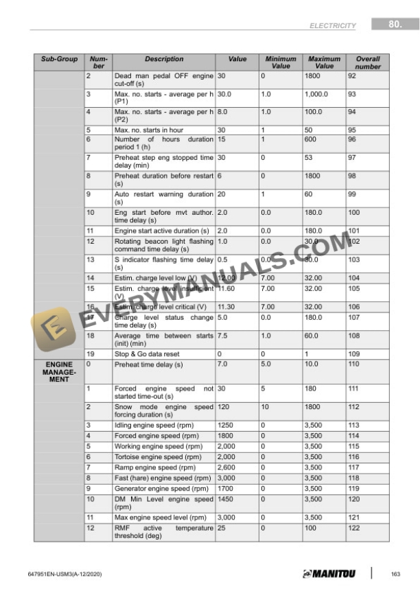
- 36.2. Program Settings
- 36.3. Manipulators Calibration
- 36.4. Joysticks Testing
- 36.5. Telescope Retracted Sensor Adjustment
- 36.6. Arm Down Sensor Adjustment
- 36.7. Tilt Calibration
- 36.8. Overload Sensors Adjustment
- 36.9. Speed calibration
- 36.10. Generator Adjustment
- 36.11. StopGo option management
- 37. Removal
- 37.1. Removing the UC234 card from the base console
- 37.2. Removing the UD22 card from the panel control base
- 38. Troubleshooting
- 38.1. Fault Codification
- 38.2. List of Alert and Default Codes
- 39. Specific tooling
- 39.1. Breakout boxes
- 40. Section Not Applicable
- 41. Control and adjustment
- 41.1. Checking Turntable rotation bearing
- 42. Section Not Applicable
- 43. Engine Diagnostic Codes (Kubota D1105E4B)
- 44. Engine Diag Codes after Treatment (Kubota D1105E4B)
- 45. Diagnostics Case (MEWP)
- 45.1. Reprogramming (FILE .H86) Parameters Access > Via RS232 UPC
- 45.2. Reprogramming (FILE .H86) Parameters Access > Via RS232 UPC
- 45.3. Reprogramming (FILE .H86) Parameters Access > Via RS232 UPC
- 45.4. Reprogramming (FILE .H86) Parameters Access > Via RS232 UPC
- 45.5. Reprogramming via CAN BUS
- 45.6. Reprogramming via CAN BUS
- 45.7. Contents of reprogramming case