Description
-
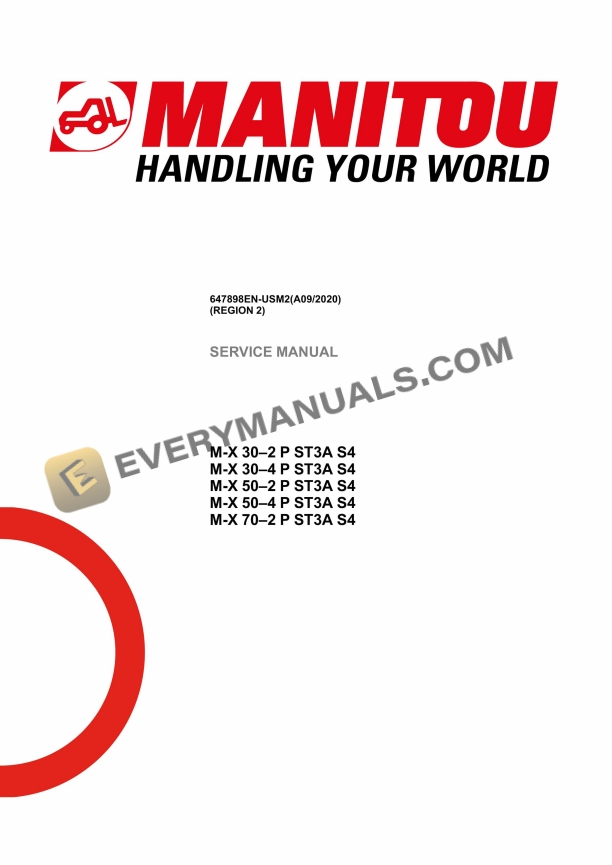
Model List:
- M-X 30-2 P ST3A S4
- M-X 30-4 P ST3A S4
- M-X 50-2 P ST3A S4
- M-X 50-4 P ST3A S4
- M-X 70-2 P ST3A S4
- 1. Legal disclaimer
- 2. TABLE OF CONTENTS
- 3. GENERAL AND SAFETY CHARACTERISTICS
- 3.1. Foreword
- 3.2. List of Abbreviations
- 3.3. Intervention during the warranty period
- 3.4. Servicing position
- 3.5. Explanation of symbols
- 3.6. Servicing Rules
- 3.7. Third party documentation list MX ST3A S4
- 3.8. Characteristics and specifications
- 3.8.1. Mass and stress MX ST3A S4
- 3.8.2. Lubricants fuels MX ST3A S4
- 3.8.3. Dimensions MX 302 P ST3A S4
- 3.8.4. Dimensions MX 304 P ST3A S4
- 3.8.5. Dimensions MX 502 P ST3A S4
- 3.8.6. Dimensions MX 504 P ST3A S4
- 3.8.7. Dimensions MX 702 P ST3A S4
- 3.9. Location
- 3.9.1. Location of name and identification plates MX ST3A S4
- 3.10. Control and adjustment
- 3.10.1. Standard tightening torques
- 3.10.2. Metric imperial unit conversion
- 4. ENGINE
- 4.1. Location
- 4.1.1. Location of engine components Perkins 1104D E3
- 4.1.2. Location of fuel system components MX ST3A S4
- 4.2. Control and adjustment
- 4.2.1. Tightening torques for silent blocks MX 30/50 ST3A S4
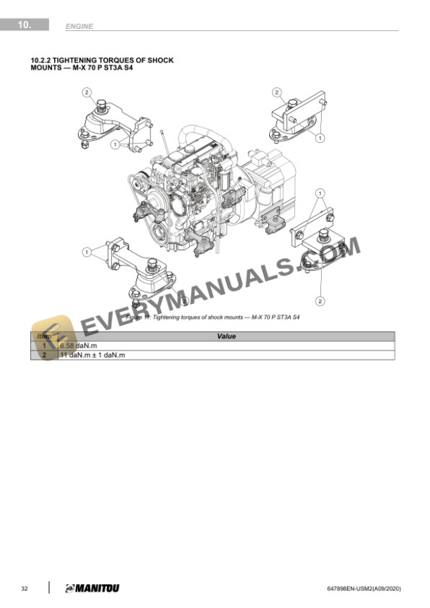
- 4.2.2. Tightening torques for silent blocks MX 70 ST3 S4
- 4.2.3. Tightening torque for air inlet MX ST3A S4
- 4.2.4. Tightening torque for alternator Perkins 1104D E3
- 4.2.5. Belt tension Perkins 1104D E3
- 4.3. Refit
- 4.3.1. Assemble the exhaust block MX ST3A S4
- 5. TRANSMISSION
- 5.1. Characteristics and specifications
- 5.1.1. Compact gearbox (MX 30, MX 50)
- 5.1.2. PowerShift T 12000 gearbox (MX 70)
- 5.2. Flow diagrams and schematic diagrams
- 5.2.1. Drive chain MX 30/502 ST3A S4
- 5.2.2. Drive chain MX 30/504 ST3A S4
- 5.2.3. Drive chain MX 702 P ST3A S4
- 5.2.4. Gearbox hydrostatic schematic diagrams MX 70 ST3A S4
- 5.3. Location
- 5.3.1. Compact gearbox (MX 30, MX 50)
- 5.3.2. PowerShift T 12000 gearbox (MX 70)
- 5.4. Control and adjustment
- 5.4.1. Tightening torques for transmission MX 30/50/702 ST3A S4
- 5.4.2. Tightening torques for transmission MX 30/504 ST3A S4
- 5.4.3. Specific settings MX 70
- 6. AXLE
- 6.1. Location
- 6.1.1. Location of the front axle cooling system MX 30/50 ST3A S4
- 6.1.2. Location of the front axle cooling system MX 702 P ST3A S4
- 6.2. Control and adjustment
- 6.2.1. Front axle (all versions)
- 6.2.2. Rear axle (4wheel drive only)
- 6.2.3. Rear axle (2wheel drive only)
- 6.3. Refit
- 6.3.1. Mount hubs on stub axles rear axle MX2
- 7. BRAKE
- 7.1. Characteristics and specifications
- 7.1.1. Characteristics of parking and service brakes MX ST3A S4
- 7.2. Flow diagrams and schematic diagrams
- 7.2.1. Diagram of parking brake MX 30/50 ST3A S4
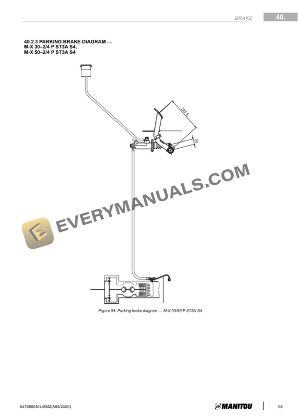
- 7.2.2. Diagram of parking brake MX 702 P ST3A S4
- 7.2.3. Diagram of service brake MX 30/50 ST3A S4
- 7.2.4. Diagram of service brake MX 702 P ST3A S4
- 7.3. Location
- 7.3.1. Overview of brake system MX 30/50 ST3A S4
- 7.3.2. Overview of brake system MX 702 P ST3A S4
- 7.4. Control and adjustment
- 7.4.1. Adjust the brake pedal MX 30/50 ST3A S4
- 7.4.2. Adjust the brake pedal MX 702 P ST3A S4
- 7.4.3. Adjust the parking brake MX 30/50 ST3A S4
- 7.4.4. Adjust parking brake cable on front axle MX 30/50 ST3A S4
- 7.4.5. Adjust the stop on TH7 MX 702 P ST3A S4
- 7.5. Specific tooling
- 7.5.1. Hydraulic brake bleed kit 554019
- 8. LIFTING STRUCTURE
- 8.1. Characteristics and specifications
- 8.1.1. Standard masts characteristics MX ST3A S4
- 8.2. Location
- 8.2.1. View of mast assembly New Mast DVT 3T
- 8.2.2. View of mast assembly New Mast TLL 3T
- 8.2.3. View of mast assembly New Mast TSLL 3T
- 8.2.4. View of mast assembly Old Mast DVT 5T
- 8.2.5. View of mast assembly Old Mast TLL 5T
- 8.2.6. View of mast assembly Old Mast DVT 7T
- 8.2.7. Kaup 466 fork positioner 294245 Location of elements
- 8.3. Control and adjustment
- 8.3.1. t masts
- 8.3.2. and 7 t masts
- 8.4. Removal
- 8.4.1. t masts
- 8.4.2. and 7 t masts
- 8.5. Refit
- 8.5.1. t masts
- 8.5.2. and 7 t masts
- 9. HYDRAULICS
- 9.1. Characteristics and specifications
- 9.1.1. Steering pump/Steering unit ospc 160 ls
- 9.2. Flow diagrams and schematic diagrams
- 9.2.1. Hydraulic schematic diagram MX 30 ST3A S4
- 9.2.2. Hydraulic schematic diagram MX 50 ST3A S4
- 9.2.3. Hydraulic schematic diagram MX 70 ST3A S4
- 9.3. Location
- 9.3.1. Location of the hydraulic pump MX 30/50/70 ST3A S4
- 9.4. Control and adjustment
- 9.4.1. Tightening torque for 3element hydraulic control valve
- 9.4.2. Adjust fork carriage damping flexibility MX ST3A S4
- 9.5. Specific tooling
- 9.5.1. Basic manometer kit
- 9.5.2. Digital manometer kit
- 9.5.3. Inflation kit
- 10. ELECTRICITY
- 10.1. Electrical Diagram Codification
- 10.1.1. Example of an electrical diagram
- 10.2. Electrical marking of cables
- 10.2.1. Cable marking on an electrical wiring harness
- 10.3. Characteristics and specifications
- 10.3.1. All versions
- 10.3.2. Components specific to the MX 70
- 10.4. Flow diagrams and schematic diagrams
- 10.4.1. Electrical schematic diagram MX 30/50 ST3A S4
- 10.4.2. Electrical schematic diagram MX 702 P ST3A S4
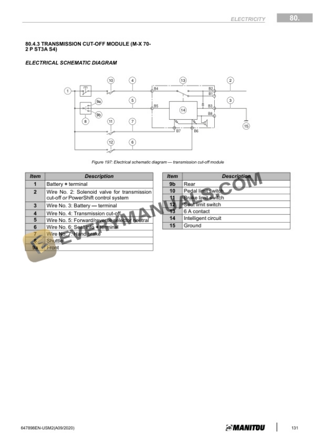
- 10.4.3. Transmission cutoff module (MX 702 P ST3A S4)
- 10.5. Location
- 10.5.1. Locations of the electrical elements of the MX 30 and MX 50
- 10.5.2. Location of the electrical elements of the MX 70
- 10.6. Control and adjustment
- 10.6.1. PowerShift T 12000 gearbox (MX 70)
- 10.6.2. EGStype shuttle lever (MX 70)
- 11. OPERATOR STATION
- 11.1. Control and adjustment
- 11.1.1. Adjust the spirit level MX ST3A S4
- 11.2. Removal
- 11.2.1. Lift the cab MX ST3A S4
- 12. CHASSIS
- 12.1. Section Not Applicable
- 13. ADDITIONAL EQUIPMENT
- 13.1. Section Not Applicable
- 14. DIAGNOSTIC TOOL AND SOFTWARE
- 14.1. Section Not Applicable