Description
-
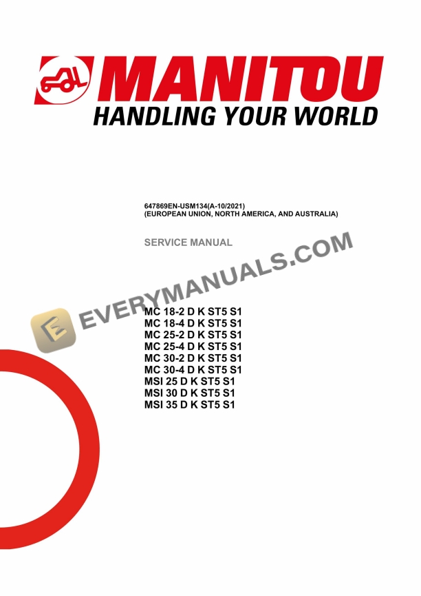
Model List:
- MC 18-2 D K ST5 S1
- MC 18-4 D K ST5 S1
- MC 25-2 D K ST5 S1
- MC 25-4 D K ST5 S1
- MC 30-2 D K ST5 S1
- MC 30-4 D K ST5 S1
- MSI 25 D K ST5 S1
- MSI 30 D K ST5 S1
- MSI 35 D K ST5 S1
- 1. Legal disclaimer
- 2. Foreword
- 3. Intervention during the warranty period
- 4. Supplier Documentation List
- 5. Safety
- 5.1. Servicing Rules
- 6. Machine Service Operations
- 6.1. Servicing position
- 6.2. Preparation and safety instructions
- 7. Characteristics and specifications
- 7.1. Technical datasheet MC 182 ST5
- 7.2. Technical datasheet MC 184 ST5
- 7.3. Technical datasheet MC 252 D K ST5 S1
- 7.4. Technical datasheet MC 254 D K ST5 S1
- 7.5. Technical datasheet MC 302 D K ST5 S1
- 7.6. Technical datasheet MC 304 D K ST5 S1
- 7.7. Technical datasheet MSI 25 D K ST5 S1
- 7.8. Technical datasheet MSI 30 D K ST5 S1
- 7.9. Technical datasheet MSI 35 D K ST5 S1
- 7.10. Lubricants Fuels
- 8. Location
- 8.1. Location of name and identification plate
- 9. Reference Information
- 9.1. Explanation of symbols
- 9.2. List of Abbreviations
- 9.3. Standard tightening torques
- 9.4. Metric imperial unit conversion
- 10. List of reference service manuals Engine
- 11. Characteristics and specifications
- 11.1. Specifications D1803CRE5 26 kW
- 11.2. Specifications D1803CRTE5 36 kW
- 12. Location
- 12.1. engine component location 26 kW
- 12.2. engine component location 36 kW
- 12.3. air intake location 26 kW
- 12.4. air intake location 36 kW
- 12.5. exhaust location 26 kW
- 12.6. exhaust location 36 kW
- 12.7. Water circuit Engine location 26 kW
- 12.8. Water circuit Engine location 36 kW
- 12.9. Fuel circuit Location 26 kW
- 12.10. Fuel circuit Location 36 kW
- 13. Control and adjustment
- 13.1. cooling check 26 kW
- 13.2. cooling check 36 kW
- 13.3. Engine suspension adjustment
- 13.4. alternator belt tension adjustment
- 14. Removal
- 14.1. DPF removal (26 kW)
- 14.2. Removal DPF (36 kW)
- 14.3. Remove the alternator belt (26Kw)
- 14.4. Remove the alternator belt (36kW)
- 14.5. Engine removal (26 kW)
- 14.6. Remove the motor (36 kW)
- 15. Troubleshooting
- 15.1. Engine Diagnostic Codes (Refer to Section 120)
- 15.2. Engine Troubleshooting Details
- 16. Specific tools
- 16.1. Electronic belt tensiometer
- 17. List of reference service manuals Engine
- 18. Characteristics and specifications
- 18.1. HYDROSTATIC PUMP A4VG CHARACTERISTICS
- 18.2. HYDROSTATIC PUMP A4VG 40 DA1D7/32R 52556872
- 18.3. HYDROSTATIC PUMP A4VG 71 DA1D7 52596962
- 18.4. HYDRAULIC WHEEL MOTOR MS05 52600979
- 18.5. HYDRAULIC WHEEL MOTOR MSE05 52577970
- 18.6. HYDRAULIC WHEEL MOTOR MG02 / MGE02 52536697
- 18.7. WHEEL DRIVE HYDROSTATIC TRANSMISSION BLOCK 52600350
- 18.8. WHEEL DRIVE HYDROSTATIC TRANSMISSION BLOCK 52541454
- 19. Schematics
- 19.1. FORWARD OPERATION FLUID DIRECTION MC 1825304WD
- 19.2. FORWARD OPERATION FLUID DIRECTION MSI 253035
- 20. Location
- 20.1. TRANSMISSION COMPONENTS LOCATION MC 2
- 20.2. TRANSMISSION COMPONENTS LOCATION MC 4
- 20.3. TRANSMISSION COMPONENTS LOCATION MSI
- 21. Control and adjustment
- 21.1. TIGHTENING TORQUE
- 21.2. Measuring, checking and adjusting pump A4VG 56 DA
- 22. Removal
- 22.1. REMOVING THE FRONT WHEEL MOTOR
- 22.2. REMOVING THE REAR WHEEL MOTOR
- 22.3. REMOVING THE HYDROSTATIC PUMP
- 23. Refit
- 23.1. Hydrostatic pump REFIT
- 23.2. Front wheel engine REFIT
- 23.3. Rear wheel engine REFIT
- 24. Specific tools
- 24.1. Basic manometer kit
- 24.2. Digital manometer kit
- 24.3. HYDROMATIK KIT (REPLACEMENT A4VGDA PUMP / A6VM MOTOR)
- 24.4. TH7 VALVE HOSE AND CONNECTOR
- 25. Control and adjustment
- 25.1. Adjusting the stops on the rear axle (4WD)
- 25.2. TIGHTENING TORQUE 2WD
- 25.3. TIGHTENING TORQUE 4WD
- 25.4. PRE STRESSING THE SPINDLE BEARINGS 2 WHEEL DRIVE
- 25.5. TURNING RADII 2 WHEEL DRIVE
- 25.6. TURNING RADII 4 WHEEL DRIVE
- 26. Refit
- 26.1. SECURE THE CONNECTING RODS
- 26.2. CASE No. 1 THE SPINDLE OR THE WHEEL MOTOR ENTERS BETWEEN THE 2 CONNECTING RODS
- 26.3. CASE No. 2 THE WHEEL MOTOR HITS THE LOWER CONNECTING ROD
- 26.4. CASE No. 3 THE WHEEL MOTOR HITS THE UPPER CONNECTING ROD
- 27. Section Not Applicable
- 28. Characteristics and specifications
- 28.1. Table Double mast specifications
- 28.2. Table Triple mast specifications
- 29. Schematics
- 29.1. DVT masts
- 29.2. TLL masts
- 29.3. TSLL masts
- 30. Control and adjustment
- 30.1. Adjust lifting cylinder New mast 3T
- 30.2. Tightening torques for mast chain New Mast 3T
- 30.3. Adjust mast lift rollers New Mast 3T
- 30.4. DVT masts
- 31. Removal
- 31.1. Remove the central lifting cylinder
- 31.2. Tilt the mast to the ground
- 31.3. Remove the free lift mast
- 31.4. Remove the lateral lifting cylinder
- 31.5. Remove the inner jamb
- 31.6. DLL masts
- 32. Refit
- 32.1. Mast chain assembly (New Mast) 3T
- 33. Characteristics and specifications
- 33.1. List of Data Sheets for Hydraulic Components
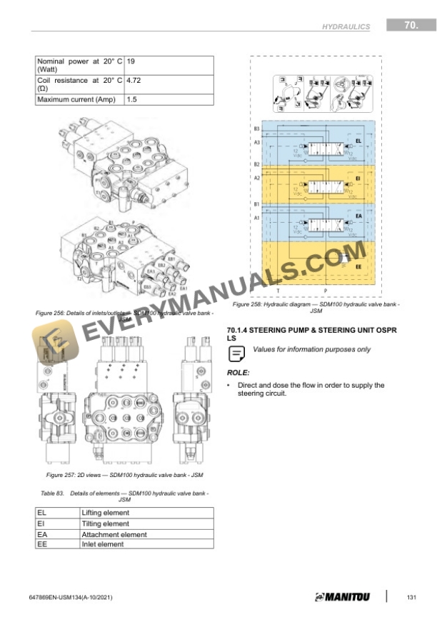
- 33.2. SDM100 hydraulic valve block
- 33.3. SDM100 hydraulic valve block JSM
- 33.4. Steering pump/Steering unit ospc 160 ls
- 33.5. PARKER 13 cm3 hydraulic pump
- 33.6. HYDRAULIC PUMP 21 cm3
- 33.7. Operation of the ECS option
- 34. Schematics
- 34.1. Hydraulic Schematic MC182
- 34.2. Hydraulic Schematic MC184
- 34.3. Hydraulic Schematic MC25302
- 34.4. Hydraulic Schematic MC25304
- 34.5. Hydraulic Schematic MSI253035
- 35. Location
- 35.1. Hydraulic local MC 1825302WD
- 35.2. Hydraulic local MC 1825304WD
- 35.3. Hydraulic local MSI 253035
- 36. Specific tools
- 36.1. Digital manometer kit
- 36.2. Basic manometer kit
- 37. Characteristics and specifications
- 37.1. Fusibles et Relais
- 37.2. Entrées/Sorties Calculateurs
- 37.3. Fiches techniques des composants électriques
- 38. Schematics
- 38.1. Functional Organization (MSI MC ST5)
- 38.2. Position by Schematics MSI MC ST5 Version PC
- 38.3. Schematics electrical MSI MC ST5 Version PC
- 38.4. Position by Schematic MSI MC ST5 Version CAB
- 38.5. Schematics electrical MSI MC ST5 Version CAB
- 38.6. Position by Schematic MSI MC ST5 Version JSM
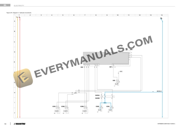
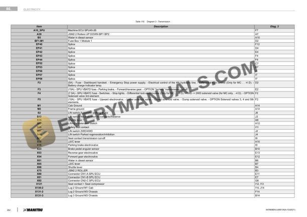
- 38.7. Schematics electrical MSI MC ST5 Version JSM
- 39. Location
- 39.1. Localization harness
- 40. Control and adjustment
- 40.1. Resetting the oil maintenance counter
- 41. Removal
- 41.1. Calculator removal
- 42. Troubleshooting
- 42.1. Diagnostic Codes (Refer to Section 120)
- 43. Specific tools
- 43.1. Solenoid adapter
- 43.2. Breakout boxes
- 44. Control and adjustment
- 44.1. Calibrate the pedals
- 45. Removal
- 45.1. Lifting the operator station
- 45.2. Raising the cabin
- 46. Removal
- 46.1. Removal of counterweight grille
- 46.2. Removal air inlet on counterweight (26 kW)
- 46.3. Counterweight removal (26 kW)
- 46.4. Remove the counterweight (36 kW)
- 47. Section Not Applicable
- 48. Default Management on the Bauser Screen
- 48.1. Fault display format
- 48.2. Reporting of a fault on the display
- 48.3. Display error counter
- 48.4. t fault code display
- 48.5. t fault code display
- 49. Machine Error Codes
- 50. Diagnostics Codes (Kubota 1803CRE5B)
- 51. Diagnostics Codes After Treatment (Kubota 1803CRE5B)
- 52. Diagnostics component
- 52.1. Component diagnostics box
- 52.2. Example of connection to the component
- 53. Diagnostics case
- 53.1. Diagnostics case
- 53.2. Example of connection to the machine
- 53.3. Accessories