Mazda 626 1995 Electrical Diagrams V6-2496cc 2.5L DOHC
$70
- Date: 1995
- Type Of Manual: Electrical Diagrams
- Engine: V6-2496cc 2.5L DOHC
- Number of Pages: 177
- Size: 24.9MB
- Format: PDF
Description
-
Model List:
- 626
- 1. Air Conditioning – Heater Circuit
- 2. Air Conditioning – Manual A_C Circuit
- 3. Anti-Lock Brakes
- 4. Anti-Theft
- 5. Body Computer
- 6. Computer Data Lines – Data Link Connector Circuit
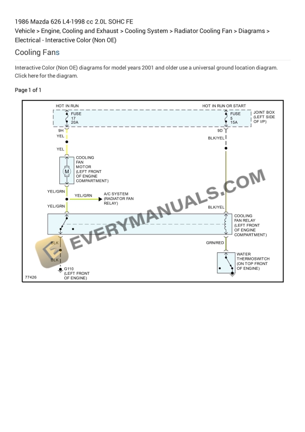
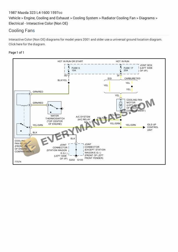
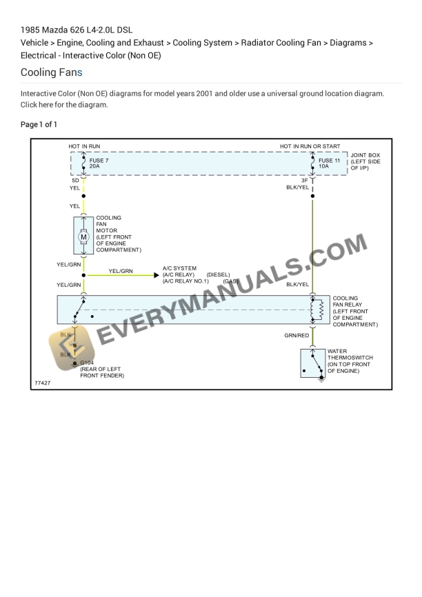
- 7. Cooling Fans
- 8. Cruise Control
- 9. Defogger
- 10. Door Locks – Door Lock Circuit
- 11. Door Locks – Keyless Entry Circuit
- 12. Engine Controls
- 13. Exterior Lights – Back-up Lamps Circuit
- 14. Exterior Lights – Exterior Lamps Circuit
- 15. Ground Distribution
- 16. Headlights – W_ DRL
- 17. Headlights – W_O DRL
- 18. Instrument Cluster
- 19. Interior Lights – Courtesy Lamp Circuit
- 20. Interior Lights – Instrument Illumination Circuit
- 21. Mirrors
- 22. Power Antenna
- 23. Power Distribution
- 24. Power Tops
- 25. Power Windows
- 26. Shift Interlock
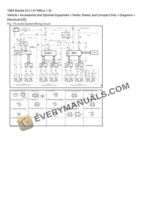
- 27. Sound Systems
- 28. Starting_Charging – Charging Circuit
- 29. Starting_Charging – Starting Circuit (A_T)
- 30. Starting_Charging – Starting Circuit (M_T)
- 31. Supplemental Restraints
- 32. Transmissions – A_T Circuit
- 33. Warning Systems
- 34. Wiper_Washer
- 35. _Short Bar_ and Diagram
- 36. A-3_001
- 37. A-3_002
- 38. A-4_001
- 39. A-4_002
- 40. A-5_001
- 41. A-5_002
- 42. Air Flow Meter_Sensor
- 43. Air Temperature Sensor ( Ambient _ Intake )
- 44. Automatic Transaxle
- 45. Automatic Transmission Control System
- 46. Canister Purge Solenoid
- 47. Central Processing Unit (CPU)
- 48. Computers and Control Systems
- 49. Coolant Line_Hose
- 50. Crankshaft Position Sensor
- 51. E-1_001
- 52. E-1_002
- 53. E-3_001
- 54. E-3_002
- 55. E-5_001
- 56. E-5_002
- 57. E-6_001
- 58. E-6_002
- 59. E-7_001
- 60. E-7_002
- 61. E-7_003
- 62. E-7_004
- 63. E-7_005
- 64. EC-AT Control System
- 65. EGR Solenoid Valve (Vacuum)
- 66. EGR Solenoid Valve (Vent)
- 67. EGR Valve Position Sensor
- 68. Emission Control Systems
- 69. Engine – Coolant Temperature Sensor_Switch
- 70. Exterior Lighting System
- 71. F-1_001
- 72. F-1_002
- 73. F-1_003
- 74. F-2_001
- 75. F-2_002
- 76. F-4_001
- 77. F-4_002
- 78. F-4_003
- 79. Fuel Delivery and Air Induction
- 80. Fuel Pressure Control Solenoid
- 81. Fuel Pump
- 82. Fuel Pump Relay
- 83. G-1A_001
- 84. G-1A_002
- 85. G-1B_001
- 86. G-1B_002
- 87. G-3_001
- 88. G-3_002
- 89. G-3_003
- 90. H-1A_001
- 91. H-1A_002
- 92. H-1B_001
- 93. H-1B_002
- 94. H-2_001
- 95. H-2_002
- 96. I-1A_001
- 97. I-1A_002
- 98. I-1A_003
- 99. I-1B_001
- 100. I-1B_002
- 101. I-2_001
- 102. I-2_002
- 103. I-2_003
- 104. I-2_004
- 105. I-2_005
- 106. I-2_006
- 107. I-4_001
- 108. I-4_002
- 109. I-4_003
- 110. I-4_004
- 111. Ignition Cable Routing
- 112. Ignition System
- 113. Interconnecting Diagram of Joint Box
- 114. J-1_001
- 115. J-1_002
- 116. J-2_001
- 117. J-2_002
- 118. K-1_001
- 119. K-1_002
- 120. K-3_001
- 121. K-3_002
- 122. K-5_001
- 123. K-5_002
- 124. K-5_003
- 125. Knock Sensor
- 126. L-1_001
- 127. L-1_002
- 128. M-1_001
- 129. M-1_002
- 130. Main Relay (Computer_Fuel System)
- 131. Manual Trans. Only
- 132. Oxygen Sensor
- 133. Q-1_001
- 134. Q-1_002
- 135. T-A_001
- 136. T-A_002
- 137. T-B_001
- 138. T-B_002
- 139. Throttle Position Sensor
- 140. U-2_001
- 141. U-2_002
- 142. Vehicle Speed Sensor
- 143. VRIS Solenoid Valve 1
- 144. VRIS Solenoid Valve 2
- 145. W-1_001
- 146. W-1_002
- 147. Wiring Diagram
- 148. Wiring Schematic
- 149. Y-2_001
- 150. Y-2_002
Related products