Compact Hydraulic Excavator Service Manual 47798001 PDF 2")
 Compact Hydraulic Excavator Service Manual 47798002 PDF 3")
 Compact Hydraulic Excavator Service Manual 47798002 PDF 4")
 Compact Hydraulic Excavator Service Manual 47798002 PDF 5")
 Compact Hydraulic Excavator Service Manual 47798002 PDF 6")
 Compact Hydraulic Excavator Service Manual 47798002 PDF 7")
Case CX36B Tier 4B (Final) Compact Hydraulic Excavator Service Manual 47798002 PDF
$30
- Type Of Manual: Service Manual
- Manual ID: 47798002
- Format: PDF
- Size: 15.7MB
- Number of Pages: 269
Description
-
Model List:
- CX36B Tier 4B (Final) Compact Hydraulic Excavator
- 1. Cover
- 2. Table of Contents
- 3. Introduction
- 4. YANMAR Warranties
- 4.1. YANMAR Limited Warranty
- 4.2. Emission System Warranty
- 4.3. YANMAR Co., Ltd. Limited Emission Control System Warranty USA Only
- 5. Safety
- 5.1. Safety Statements
- 5.2. Safety Precautions
- 6. General Service Information
- 6.1. Component Identification
- 6.2. Location of Labels
- 6.3. Emission Control Regulations
- 6.4. Emission Control Labels
- 6.5. Engine Family
- 6.6. Function of Major Engine Components
- 6.7. Main Electronic Control Components and Features
- 6.8. Function of Cooling System Components
- 6.9. Diesel Fuel
- 6.10. Engine Oil
- 6.11. Engine Coolant
- 6.12. Specifications
- 6.13. Principal Engine Specifications
- 6.14. Engine Service Standards
- 6.15. Tightening Torques for Standard Bolts and Nuts
- 6.16. Abbreviations and Symbols
- 6.17. Unit Conversions
- 7. Periodic Maintenance
- 7.1. Before You Begin Servicing
- 7.2. Introduction
- 7.3. Periodic Maintenance Schedule
- 7.4. Periodic Maintenance Procedures
- 8. Engine
- 8.1. Before You Begin Servicing
- 8.2. Introduction
- 8.3. Cylinder Head Specifications
- 8.4. Camshaft and Timing Gear Train Specifications
- 8.5. Crankshaft and Piston Specifications
- 8.6. Cylinder Block Specifications
- 8.7. Special Torque Chart
- 8.8. Special Service Tools
- 8.9. Measuring Instruments
- 8.10. Cylinder Head
- 8.11. Measuring and Adjusting Valve Clearance
- 8.12. Crankshaft and Camshaft Components
- 8.13. EGR system
- 9. Fuel System
- 9.1. Before You Begin Servicing
- 9.2. Fuel System Specifications
- 9.3. Special Service Tools
- 9.4. Measuring Instruments
- 9.5. Fuel System Diagram
- 9.6. Fuel System Components
- 9.7. Fuel Injection Pump
- 9.8. Checking and Adjusting Fuel Injection Timing
- 9.9. Fuel Injectors
- 10. Cooling System
- 10.1. Before You Begin Servicing
- 10.2. Introduction
- 10.3. Cooling System Diagram
- 10.4. Engine Coolant Pump Components
- 10.5. Engine Coolant System Check
- 10.6. Engine Coolant Pump
- 11. Lubrication System
- 11.1. Before You Begin Servicing
- 11.2. Introduction
- 11.3. Oil Pump Service Information
- 11.4. Lubrication System Diagram
- 11.5. Checking Engine Oil Pressure
- 11.6. Trochoid Oil Pump
- 12. Starter Motor
- 12.1. Before You Begin Servicing
- 12.2. Introduction
- 12.3. Starter Motor Information
- 12.4. Starter Motor Specifications
- 12.5. Starter Motor Troubleshooting
- 12.6. Starter Motor Components
- 12.7. Starter Motor
- 13. Alternator
- 13.1. Before You Begin Servicing
- 13.2. Introduction
- 13.3. Dynamo and Alternator Information
- 13.4. Alternator Specifications
- 13.5. Dynamo Specifications
- 13.6. Alternator Troubleshooting
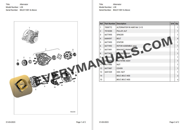
- 13.7. Alternator Components
- 13.8. Alternator Wiring Diagram
- 13.9. Alternator Standard Output
- 13.10. Alternator
- 13.11. Dynamo Component Location
- 13.12. Dynamo Wiring Diagram
- 13.13. Operation of Dynamo
- 13.14. Dynamo Standard Output
- 13.15. Testing of Dynamo
- 13.16. Dynamo
- 14. ELECTRONIC CONTROL SYSTEM
- 14.1. Before You Begin Servicing
- 14.2. Introduction
- 14.3. Electronic Control System
- 14.4. Electronic control harness connections
- 15. Electric Wiring
- 15.1. Electric Wiring Precautions
- 15.2. Electrical Wire Resistance
- 15.3. Battery Cable Resistance
- 15.4. Electrical Wire Sizes Voltage Drop
- 15.5. Conversion of AWG to European Standards
- 16. Failure Diagnosis
- 16.1. Special Service Tools
- 16.2. Troubleshooting By Measuring Compression Pressure
- 16.3. Quick Reference Table For Troubleshooting