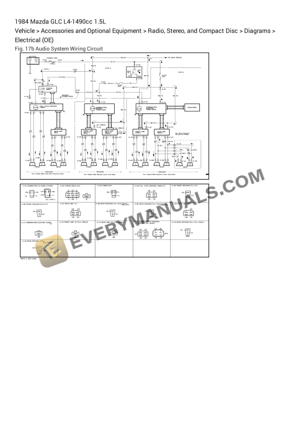
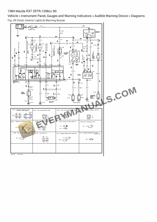
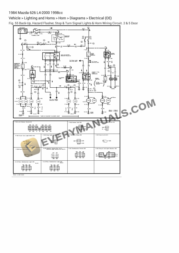
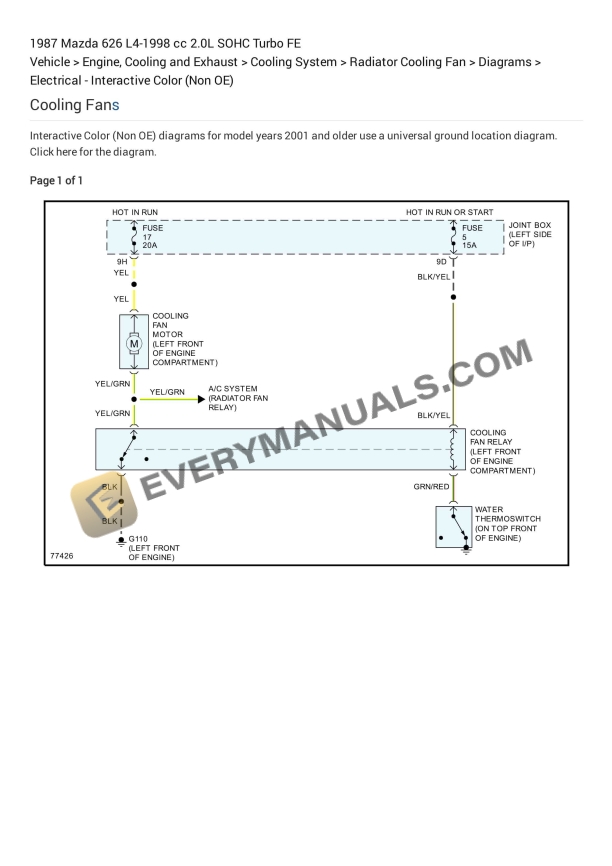
Mazda MX-3 1994 Electrical Diagrams V6-1844cc 1.8L DOHC
$70
- Date: 1994
- Type Of Manual: Electrical Diagrams
- Engine: V6-1844cc 1.8L DOHC
- Number of Pages: 202
- Size: 21.5MB
- Format: PDF
Description
-
Model List:
- MX-3
- 1. Air Conditioning – Heater Circuit
- 2. Air Conditioning – Manual A_C Circuit (A_T)
- 3. Air Conditioning – Manual A_C Circuit (M_T)
- 4. Anti-Lock Brakes
- 5. Body Computer – Central Processing Unit Circuit
- 6. Computer Data Lines – Data Link Connector Circuit
- 7. Cooling Fans – A_T
- 8. Cooling Fans – M_T
- 9. Cruise Control
- 10. Defogger
- 11. Door Locks
- 12. Engine Controls – A_T
- 13. Engine Controls – M_T
- 14. Exterior Lights
- 15. Ground Distribution
- 16. Headlights – W_ DRL amp W_ Air Bag
- 17. Headlights – W_ DRL amp W_O Air Bag
- 18. Headlights – W_O DRL
- 19. Instrument Cluster
- 20. Interior Lights
- 21. Mirrors
- 22. Power Distribution
- 23. Power Tops
- 24. Power Windows
- 25. Shift Interlock
- 26. Sound Systems
- 27. Starting_Charging – Charging Circuit
- 28. Starting_Charging – Starting Circuit (A_T)
- 29. Starting_Charging – Starting Circuit (M_T)
- 30. Supplemental Restraints
- 31. Transmissions – A_T Circuit
- 32. Warning Systems
- 33. Wiper_Washer – Front Wiper_Washer Circuit
- 34. Wiper_Washer – Rear Wiper_Washer Circuit
- 35. Shift Solenoid Valve
- 36. Shift Solenoid Valve
- 37. Shift Solenoid Valve
- 38. A-1 MTX_001
- 39. A-1 MTX_002
- 40. A-1 MTX_003
- 41. A-2 ATX_001
- 42. A-2 ATX_002
- 43. A-2 ATX_003
- 44. A_C Signal
- 45. Air Flow Meter_Sensor
- 46. B-2A_001
- 47. B-2A_002
- 48. B-2B_001
- 49. B-2B_002
- 50. B-2C_001
- 51. B-2C_002
- 52. B-3_001
- 53. B-3_002
- 54. B-4 MTX_001
- 55. B-4 MTX_002
- 56. B-5 ATX
- 57. C-2A_001
- 58. C-2A_002
- 59. C-2B_001
- 60. C-2B_002
- 61. Circuit Diagram
- 62. Crankshaft Position Sensor 1
- 63. Crankshaft Position Sensor 2
- 64. D-1_001
- 65. D-1_002
- 66. D-1_003
- 67. D-2_001
- 68. D-2_002
- 69. D-2_003
- 70. E-1_001
- 71. E-1_002
- 72. E-2_001
- 73. E-2_002
- 74. E-3 (Canada)
- 75. E-4_001
- 76. E-4_002
- 77. E-4_003
- 78. E-4_004
- 79. E-4_005
- 80. EC-AT Control System
- 81. EGR Control Solenoid
- 82. EGR Valve Position Sensor
- 83. Engine – Coolant Temperature Sensor_Switch
- 84. F-1_001
- 85. F-1_002
- 86. F-1_003
- 87. F-2_001
- 88. F-2_002
- 89. F-2_003
- 90. F-3_001
- 91. F-3_002
- 92. G-2_001
- 93. G-2_002
- 94. G-4 (With Logical Mode Control)
- 95. H-2_001
- 96. H-2_002
- 97. H-3_001
- 98. H-3_002
- 99. I-1_001
- 100. I-1_002
- 101. I-1_003
- 102. I-2_001
- 103. I-2_002
- 104. I-2_003
- 105. I-3_001
- 106. I-3_002
- 107. I-3_003
- 108. Ignition Coil
- 109. Ignition Control Module
- 110. Ignition System Schematic
- 111. Interconnecting Diagram of Joint Box
- 112. J-1 (Option)
- 113. K-1_001
- 114. K-1_002
- 115. K-2_001
- 116. K-2_002
- 117. Knock Sensor
- 118. O-1 (4 Wheel Antilock Brake System (4WABS))
- 119. Oxygen Sensor
- 120. Part 1 of 2_001
- 121. Part 1 of 2_002
- 122. Part 2 of 2_001
- 123. Part 2 of 2_002
- 124. System Schematic
- 125. Throttle Position Sensor
- 126. U-2_001
- 127. U-2_002
- 128. Wiring Diagram
- 129. With Automatic Transaxle_001
- 130. With Automatic Transaxle_002
- 131. With Manual Transaxle_001
- 132. With Manual Transaxle_002
Related products